Most Sinzing
| Kategorie | Infrastrukturprojekte |
|---|---|
| Jahr | 2025 |
| Land | Poland |
| Organisation | MTA Engineering Sp. z o.o. |
| Projektpartner | Max Bögl |
| Verfasser | MTA Engineering Sp. z o.o. |
| Auftraggeber | Max Bögl |
| Ort des Bauwerkes | Niemcy |
| Tags | Tekla StructuresTrimble ConnectSteel |
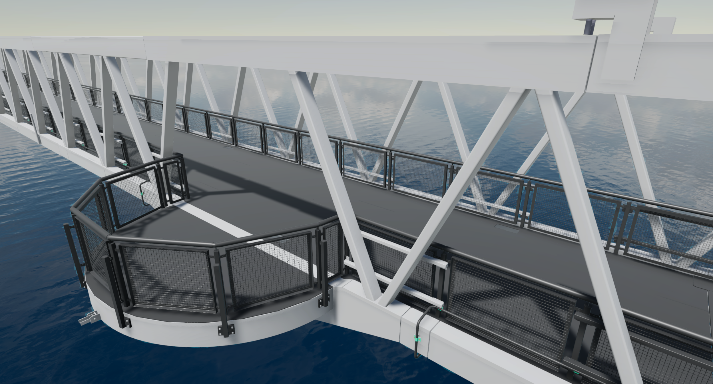
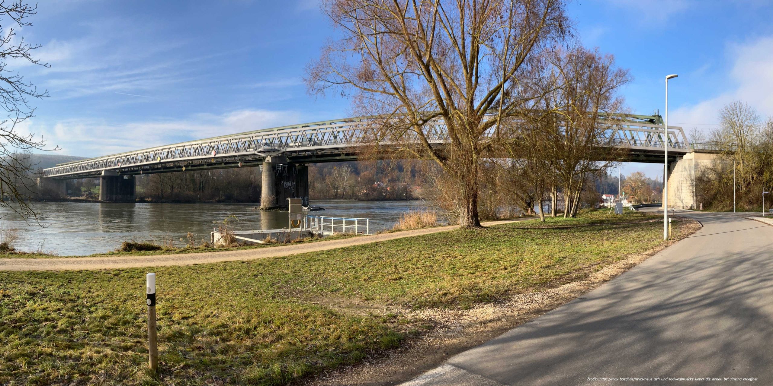
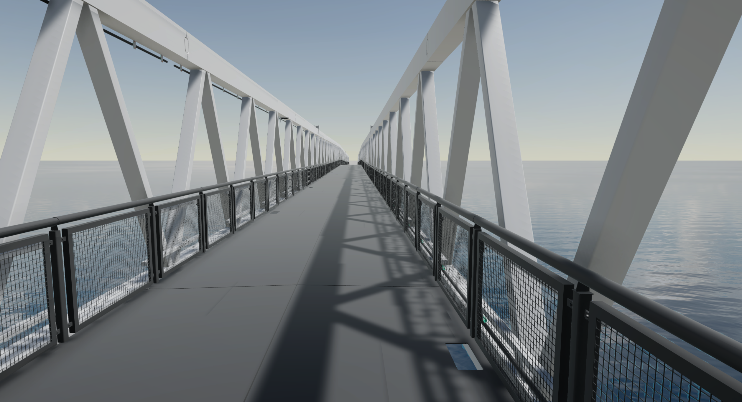
Biuro projektów MTA Engineering na zlecenie wykonawcy zrealizowało dokumentację warsztatową i montażową konstrukcji stalowej mostu dla pieszych i rowerzystów nad Dunajem w pobliżu malowniczej gminy Sinzing, koło Regensburga w Niemczech. Planowanie oraz obliczenia zostały wykonane przez IGS Ingenieure oraz bulicek + ingenieure GmbH.
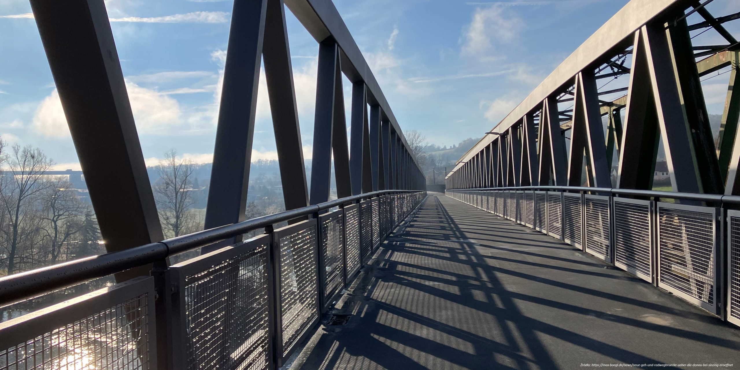
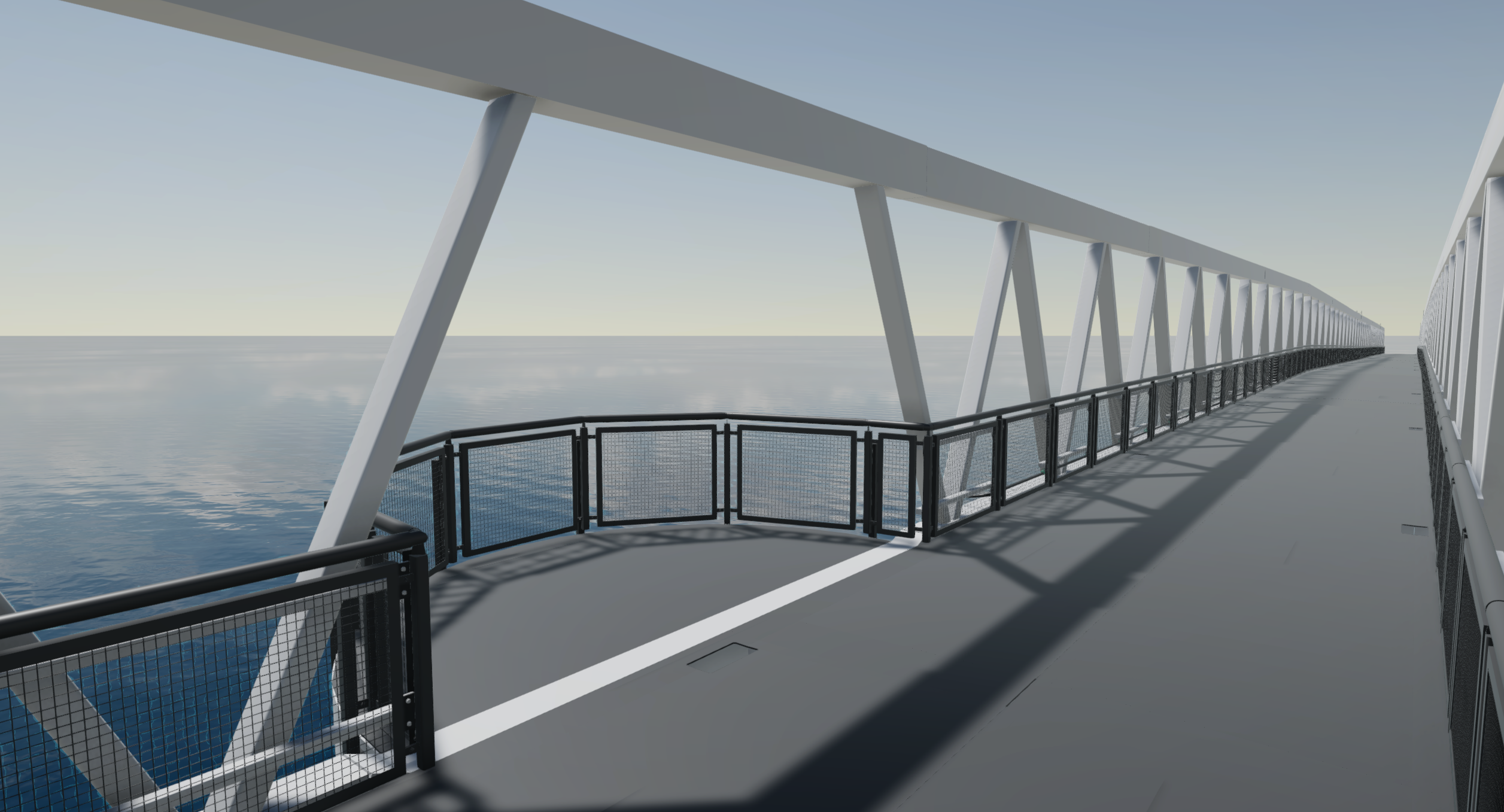
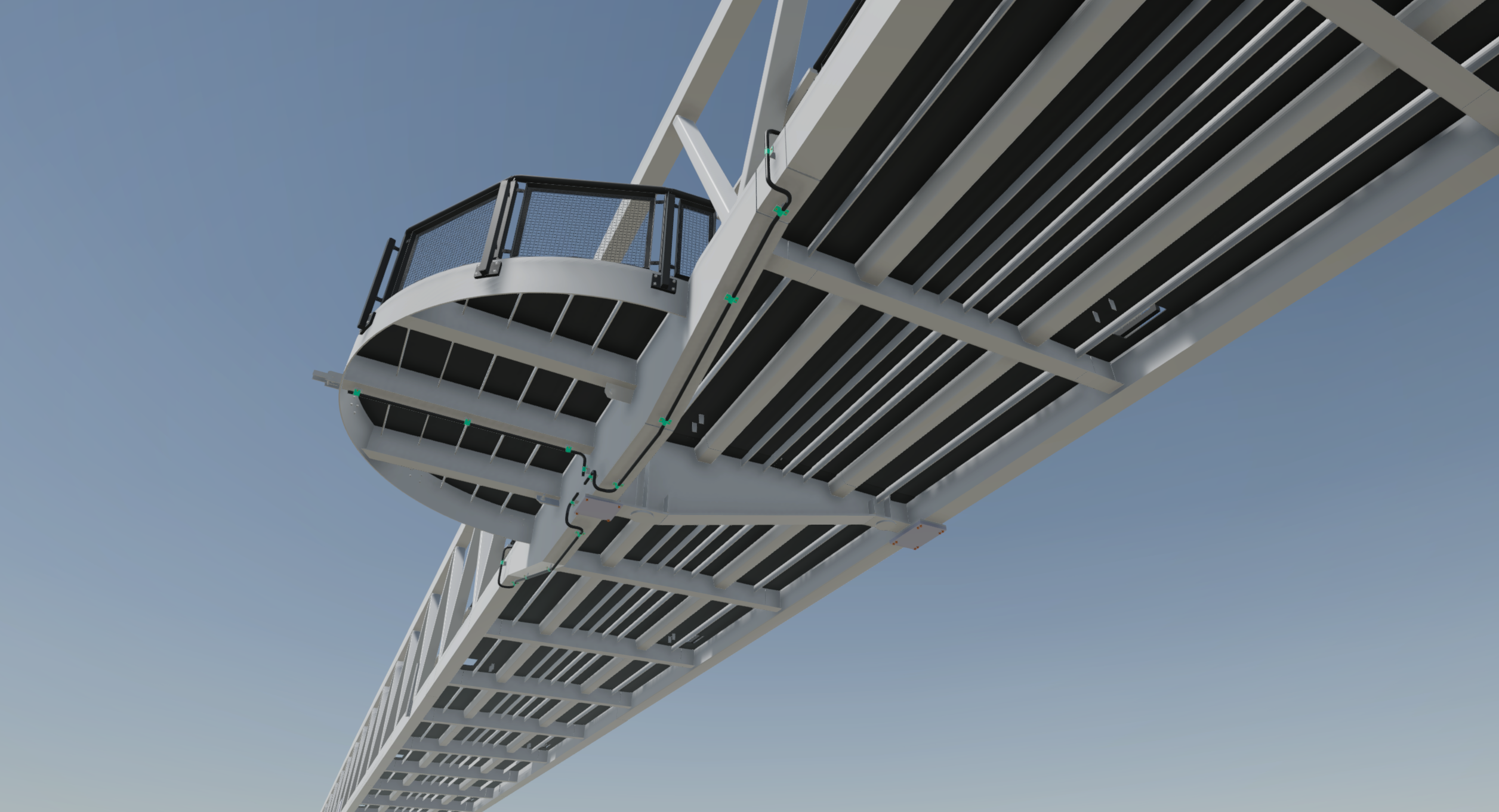
Stalowa konstrukcja nośna o masie 365 ton została zaprojektowana jako kratownicowy most z ortotropową jezdnią. Dźwigary kratownicowe o stałej wysokości konstrukcyjnej są zbudowane z profili zamkniętych.
W programie Tekla Structures wykonany został kompletny model 3d wraz z planami montażowymi, dokumentacją warsztatową i plikami NC dla obrabiarek sterowanych numerycznie. Dla płyty jezdnej korzystano z funkcji Tekli do wyznaczania lokalizacji elementów dochodzących, które maszynowo były oznaczane na elementach stalowych. Ze względu na skurcz w trakcie spawania wykorzystano narzędzie Tekla do wydłużania pozycji. Fazowania na krawędziach blach pod spoiny doczołowe wykonano nawet w pozycjach wygiętych w dwóch płaszczyznach.
The design office MTA Engineering on behalf of the contractor completed the workshop and assembly documentation for the steel structure of the pedestrian and cycle bridge over the river Danube near the picturesque village of Sinzing, near Regensburg. Planning and calculations were carried out by IGS Ingenieure and bulicek + ingenieure GmbH.
The 365-tonne steel superstructure was designed as a truss bridge with an orthotropic steel deck. The constant-height truss girders are constructed from hollow sections.
A complete 3d model was made in Tekla Structures, together with assembly plans, workshop documentation and NC files for numerically controlled machine tools. For the deck plate, Tekla functions were used to determine the location of the ascending longitudinal ribs, which were machine-marked on the steel elements. Due to shrinkage during welding, the Tekla tool was used to extend the positions. Chamfers on the edges of the plates for butt welds were made even in positions bent in two dimensions.

Hinterlasse ein Kommentar
Construsoft is an authorized Tekla Structures vendor and provides training, technical support, and other services to its customers.
For more information, please visit our website:
construsoft.comTekla is a Trimble Company © Copyright 2026 Tekla