 Vencedor da categoria nos países:
Letiště, Francie
| Categoria | Projectos Públicos |
|---|---|
| Ano | 2020 |
| País | Czech Republic |
| Organização | Industrial Design & Service a.s. & Promstal engineering, s.r.o. |
| Autor | Ing. Petr Otáhal (Promstal engineering s.r.o.), Ing. Vladimír Snopek (Industrial Design & Service a.s.) |
| Co-autores | Industrial Design & Service a.s.: Ing. Jiří Tvrdý, Ing. Pavel Lánský, Šárka Špicarová, Promstal engineering s.r.o.: Ing. Miroslav Čecháček, Jan Richter, Ing. Ondřej Ceh, Ing. Pavel Stibor |
| Cliente | SGS Industrial Services CZ s.r.o. |
| Local de construção | Francie |
| Tags |
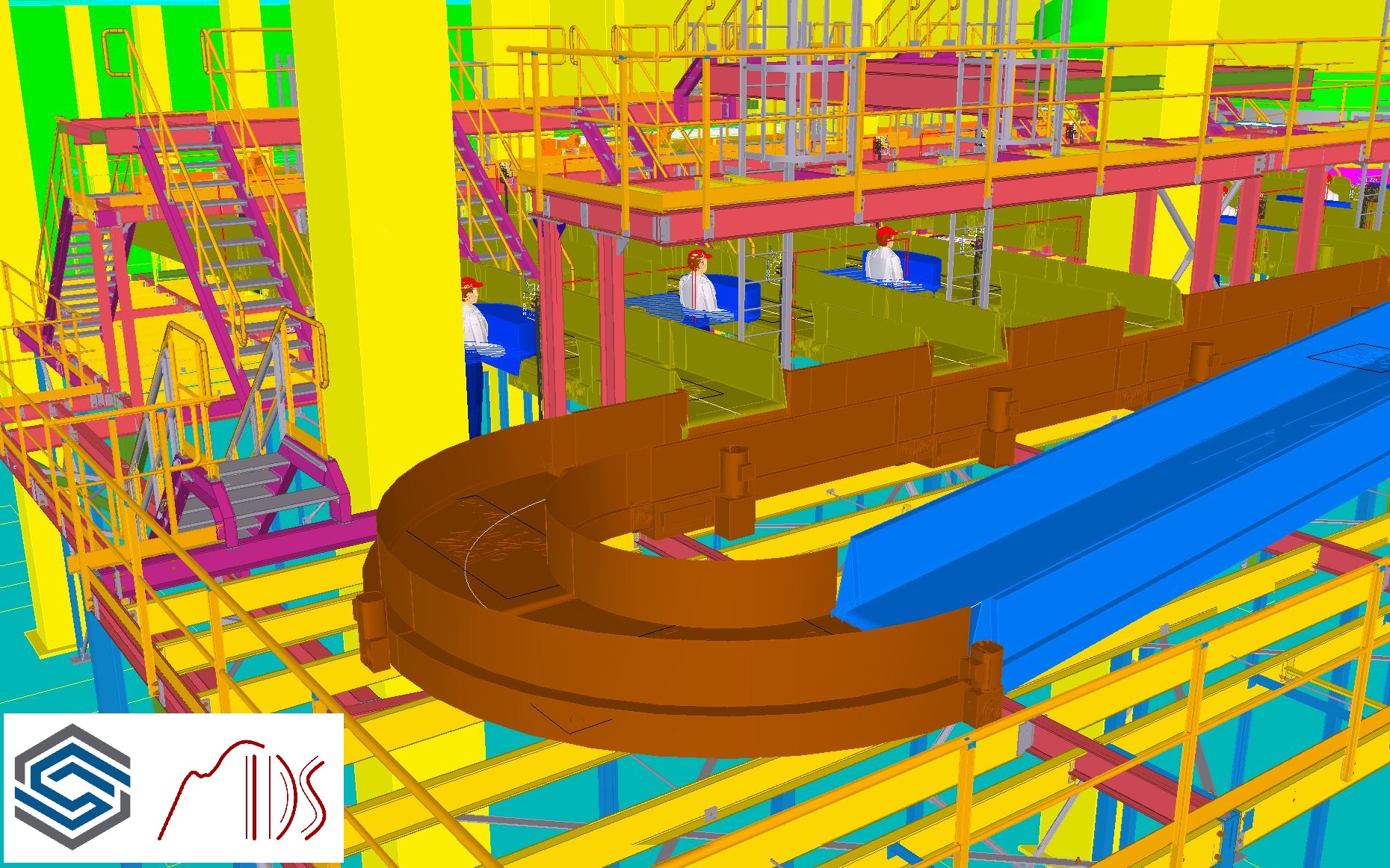
Je nesporným faktem, že bez moderních nástrojů Tekla Structures Steel Detailling, Tekla Sharing a Trimble Connect by celý proces nemohl běžet takovým tempem a s takovou kvalitou. Veškeré předávání podkladů a zadání probíhalo formou 3D modelů a dat.
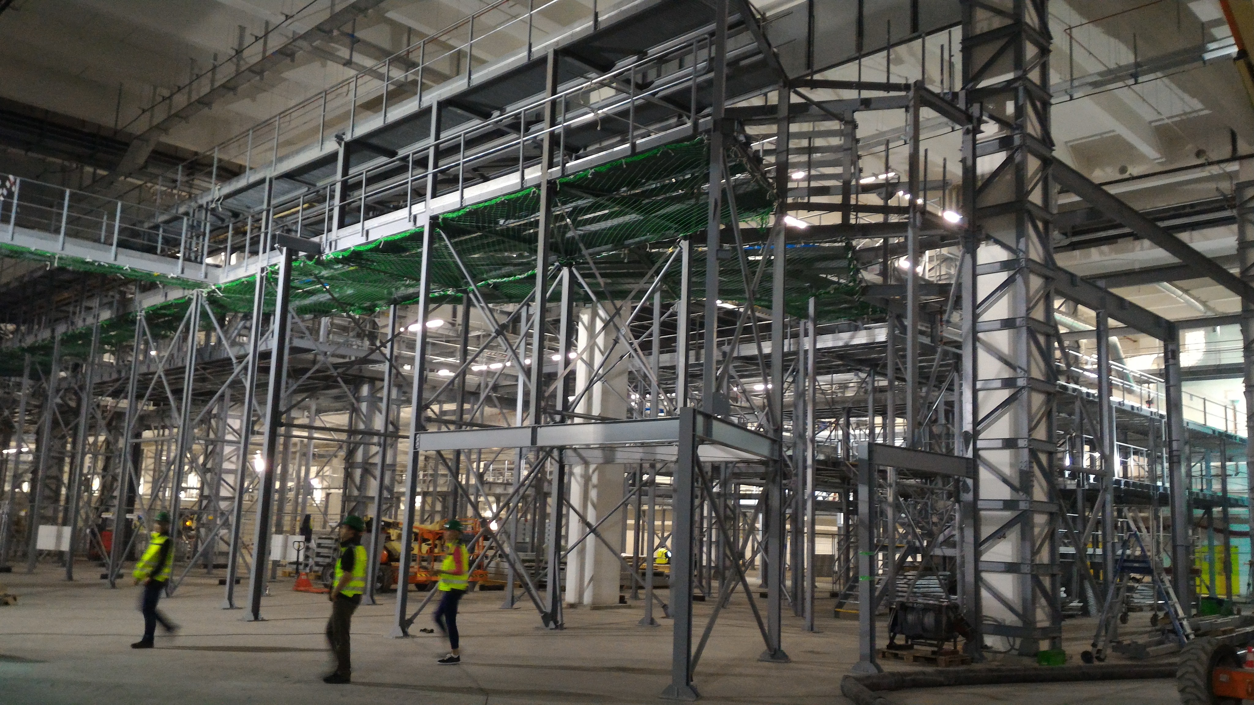
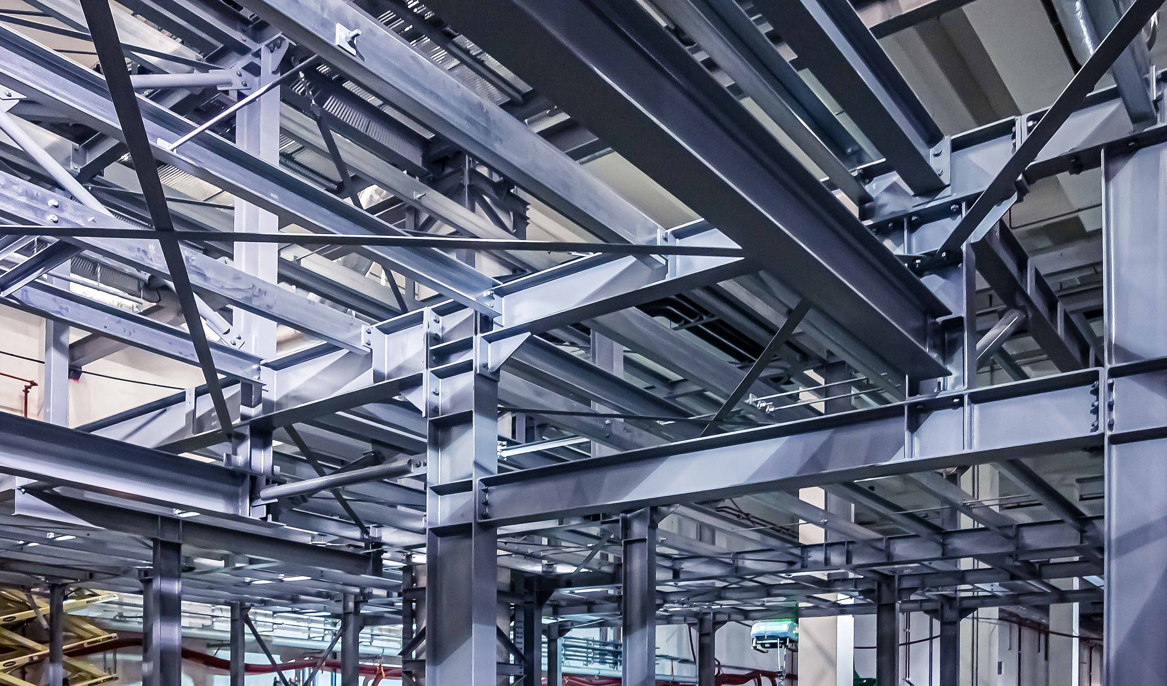
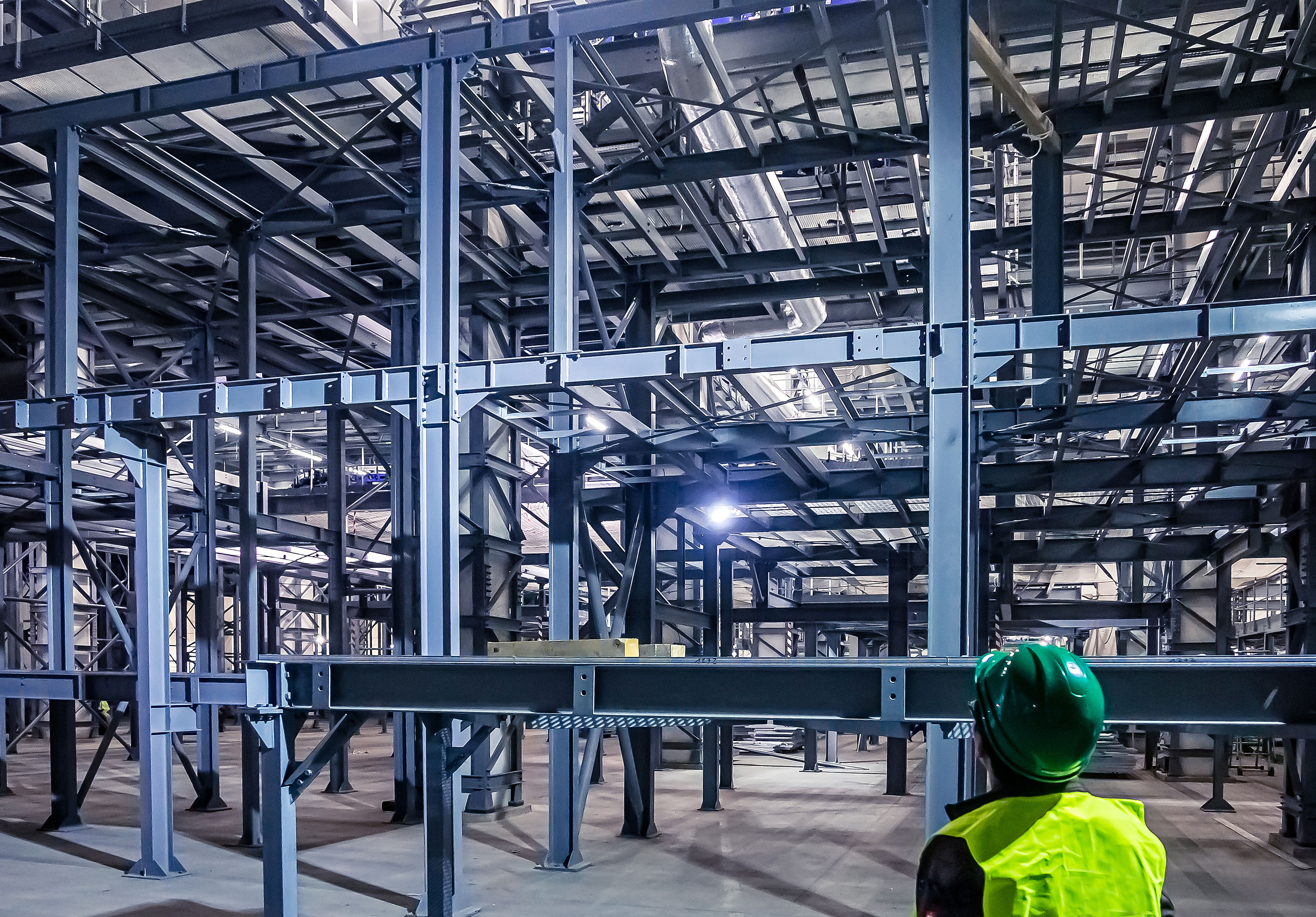
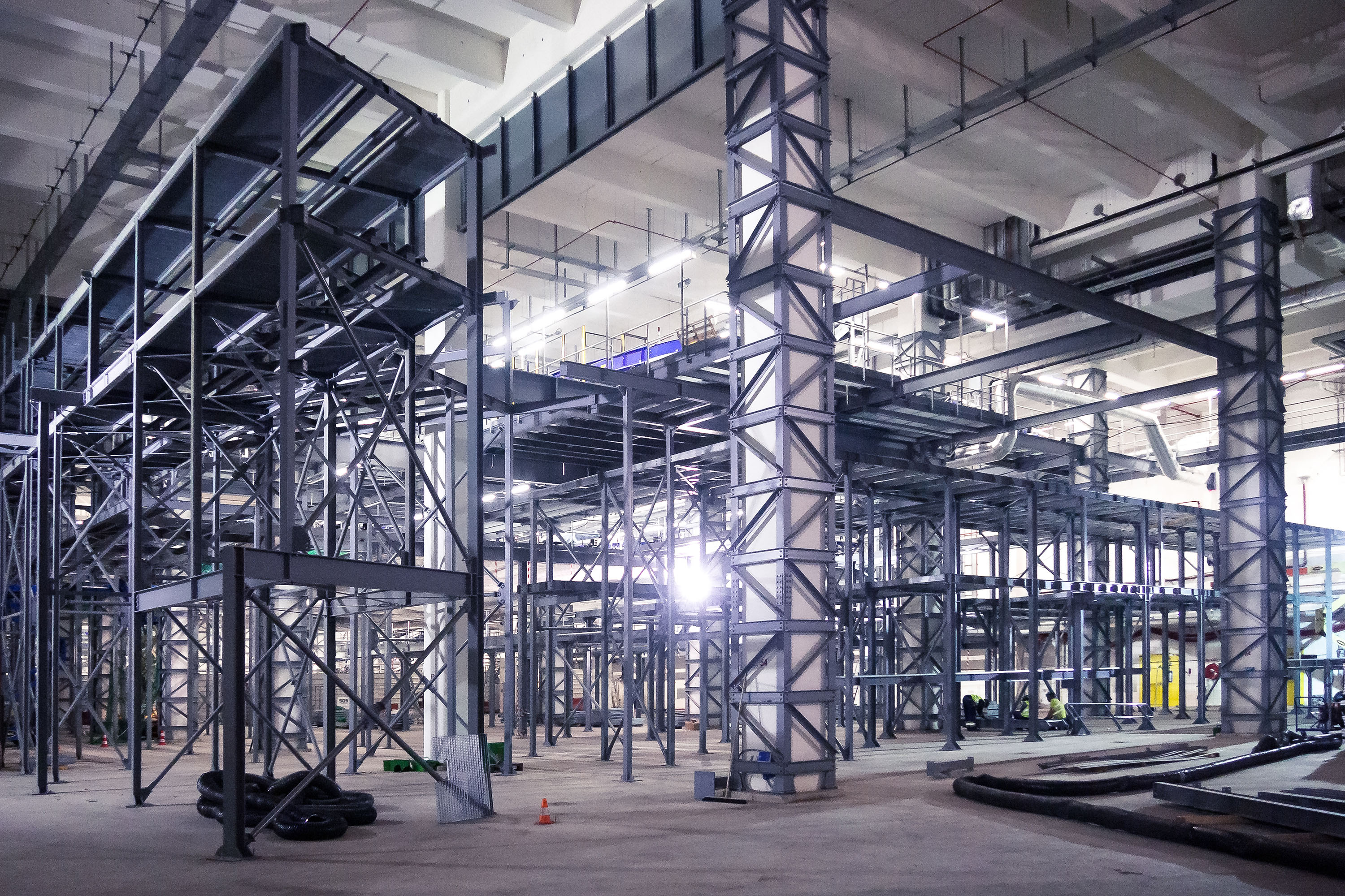
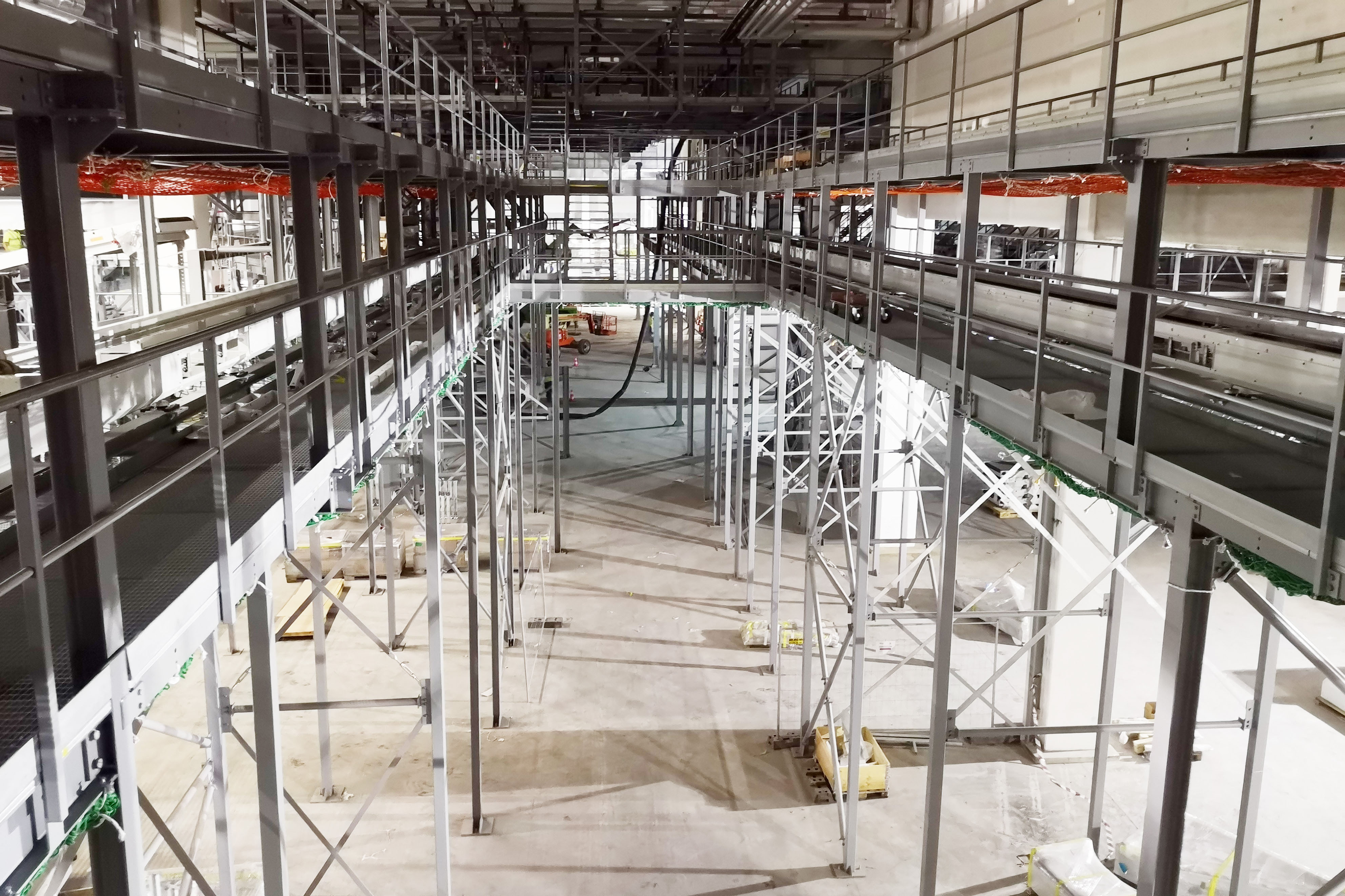
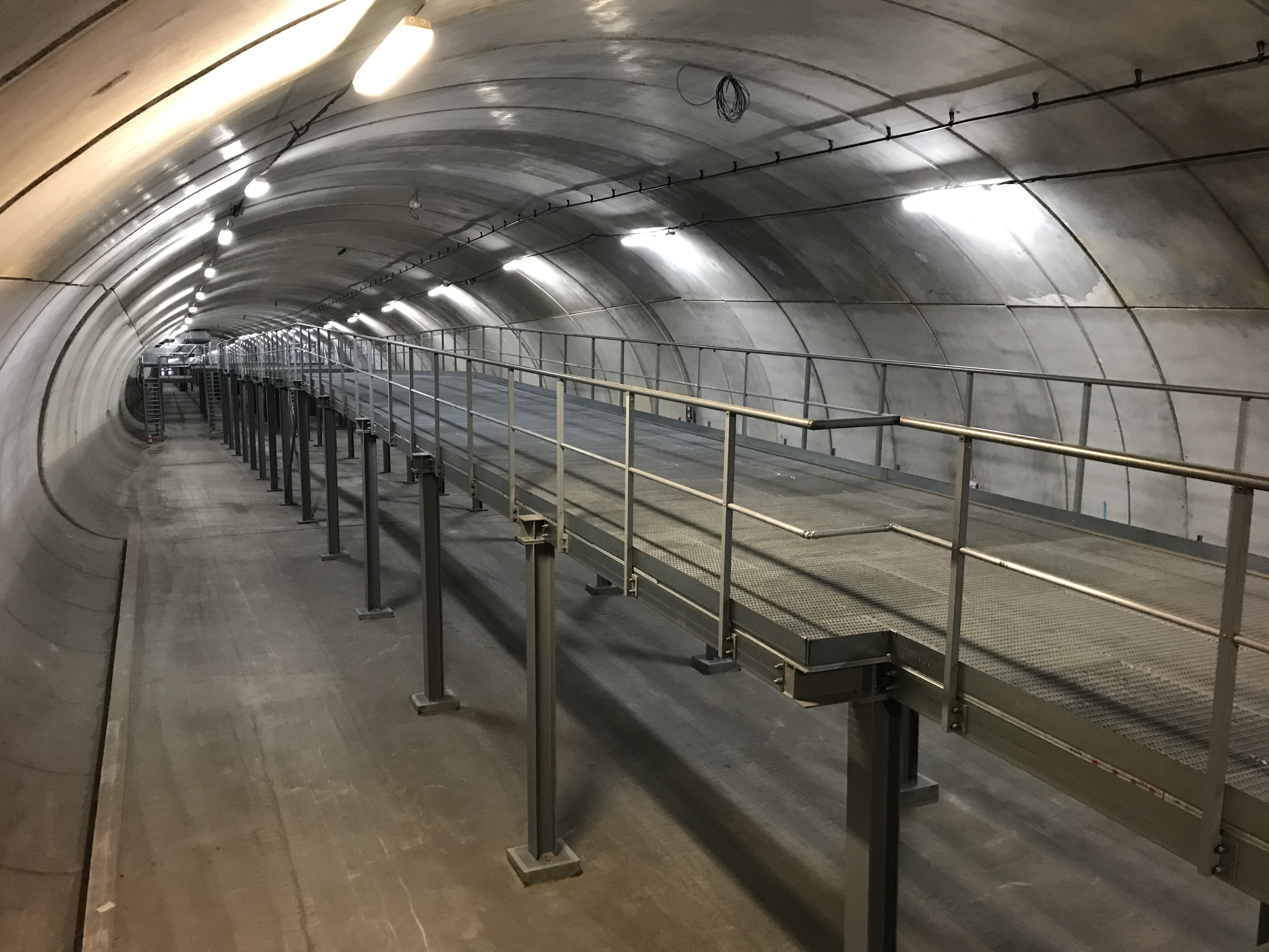
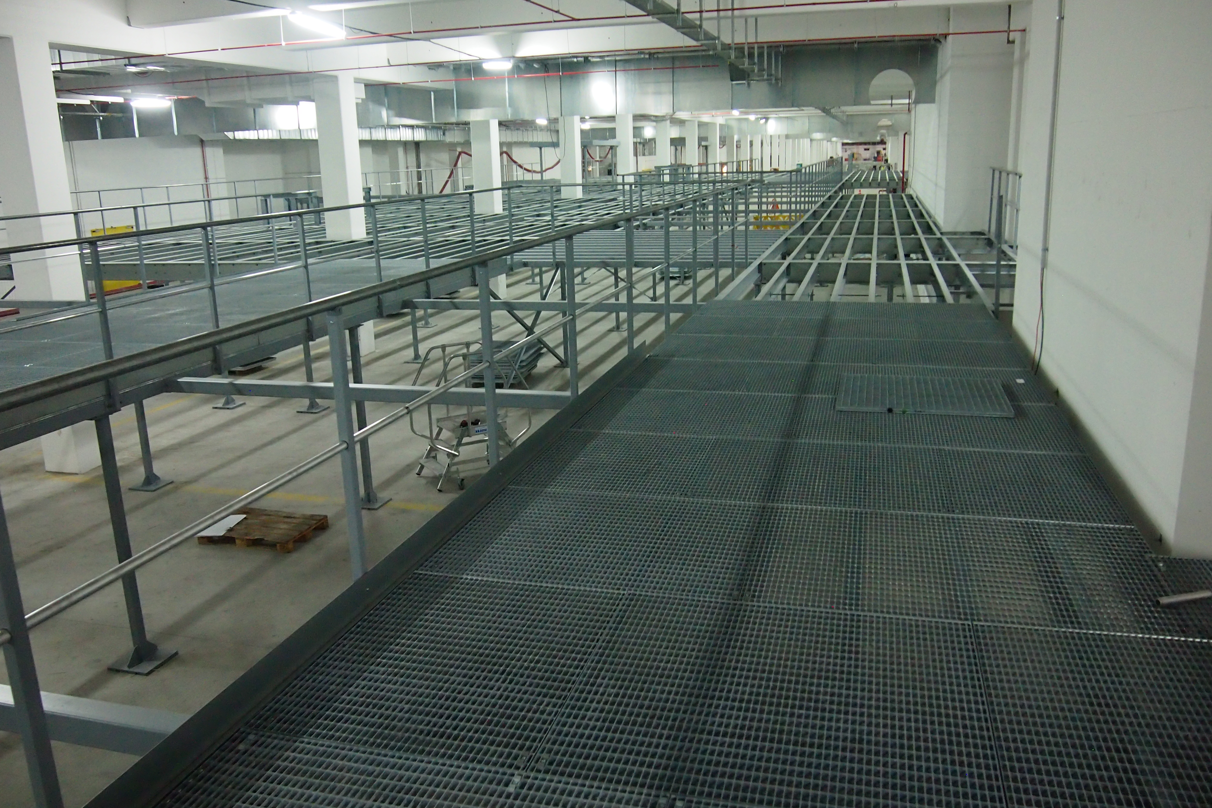
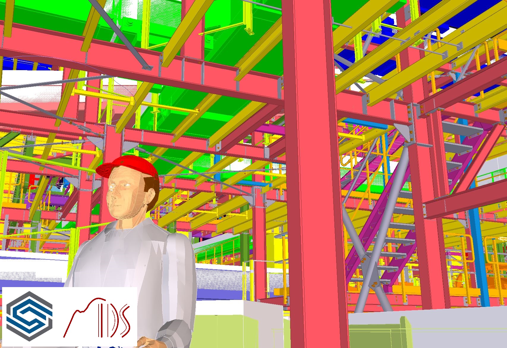
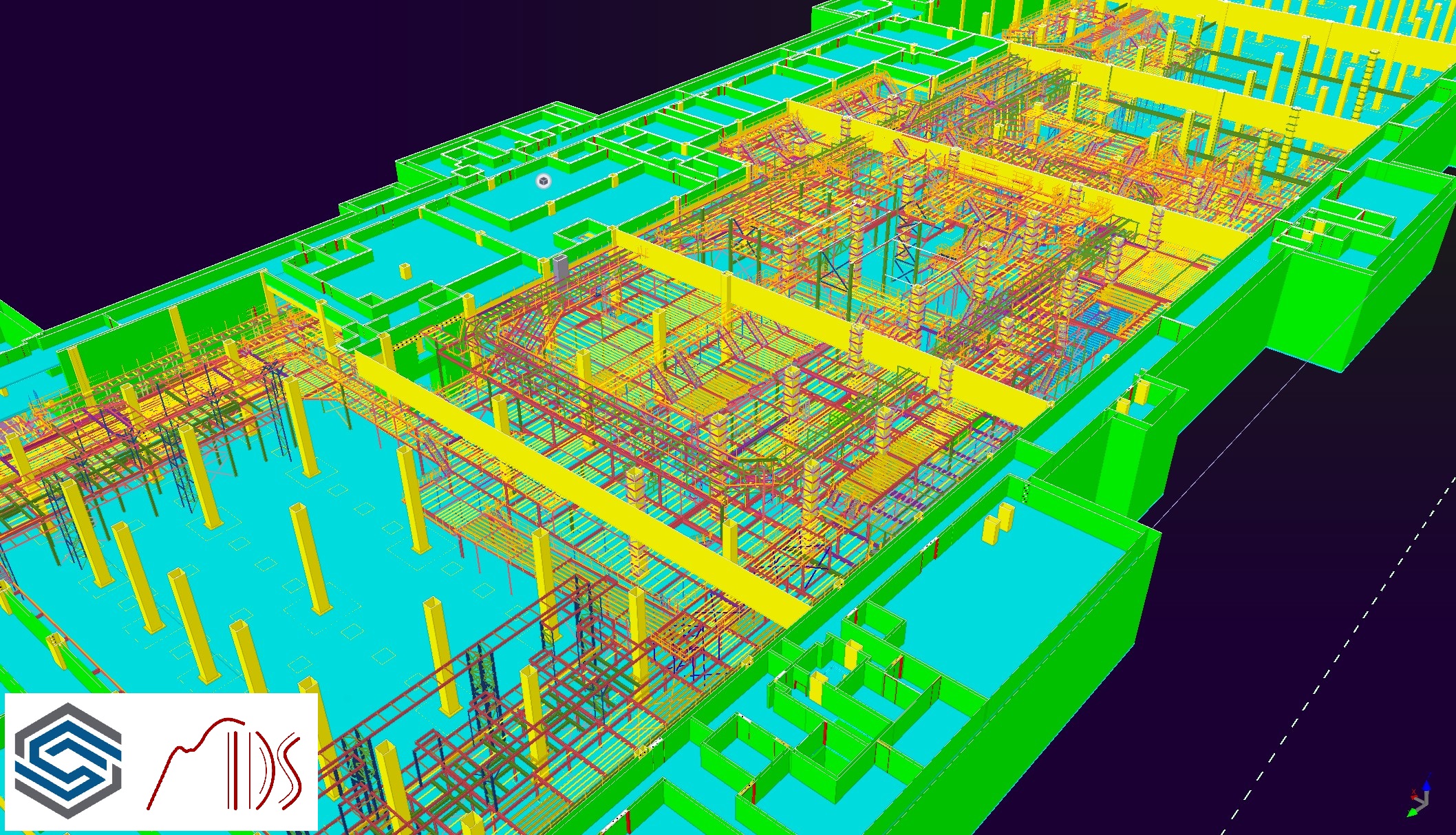
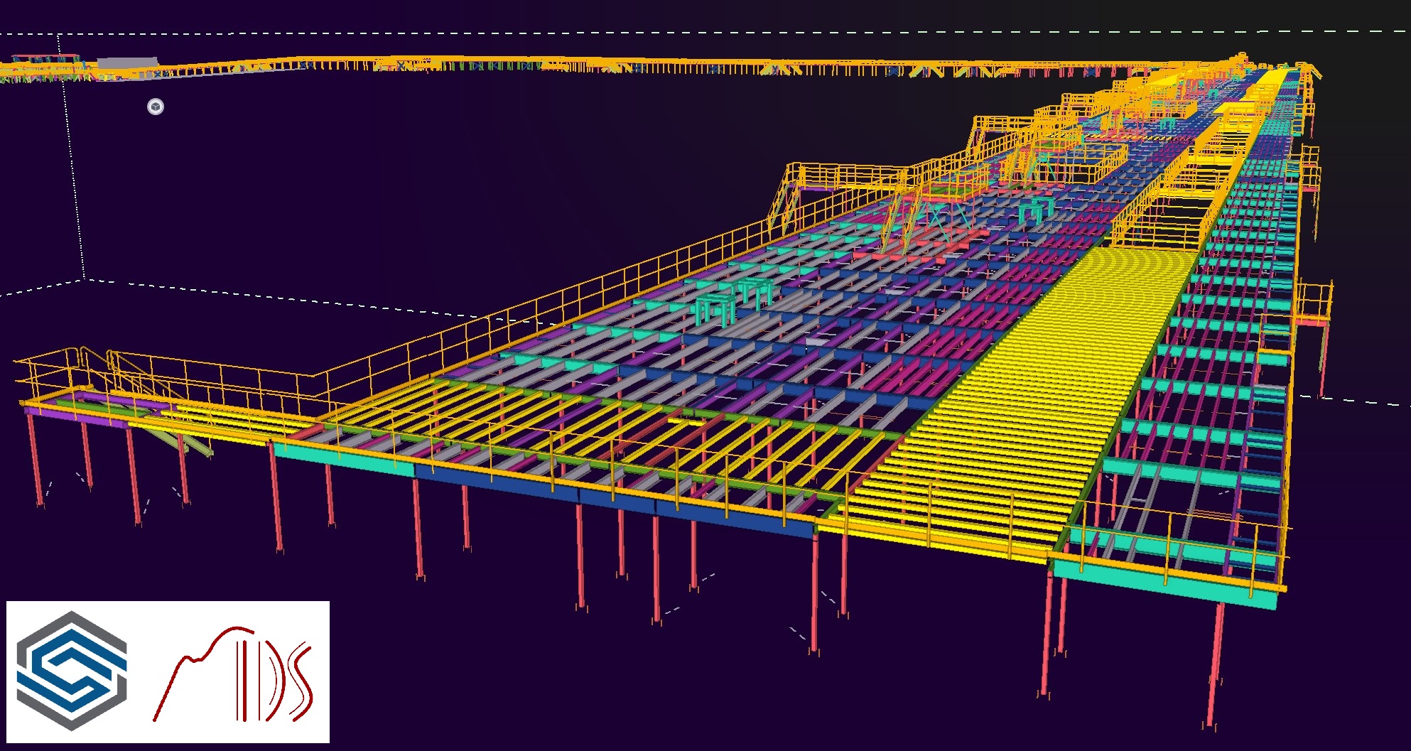
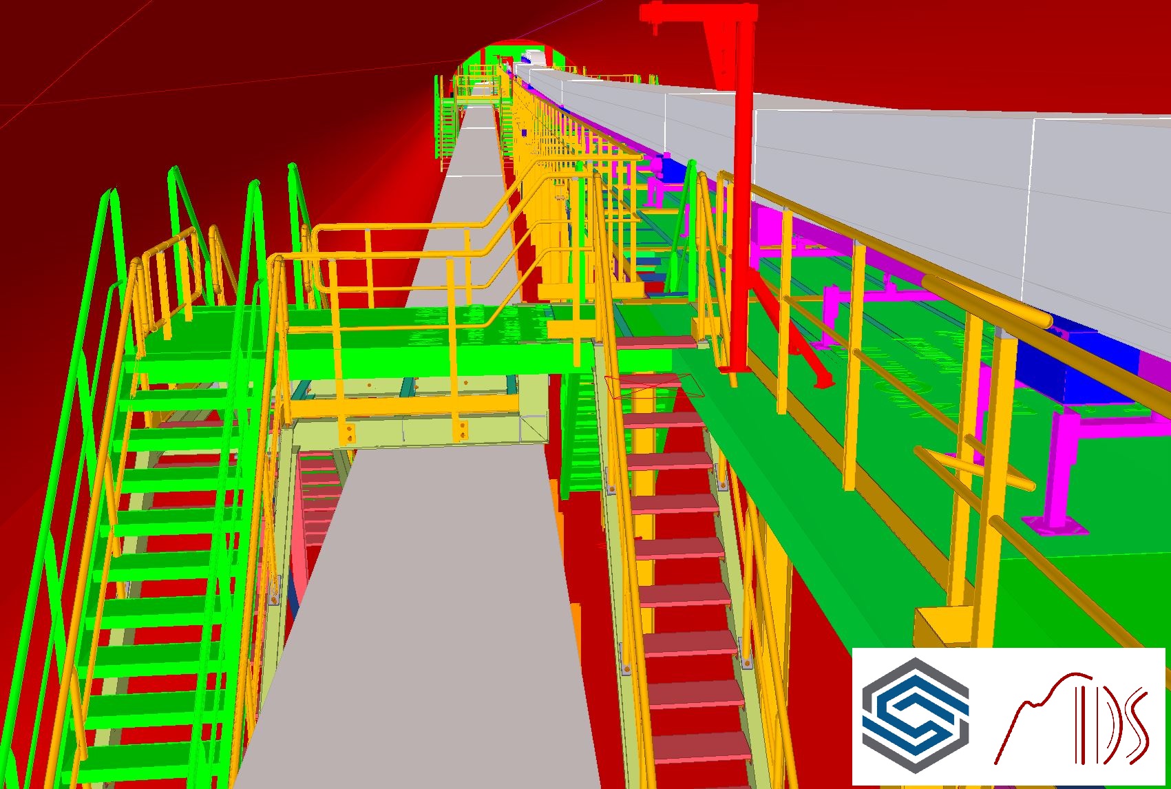
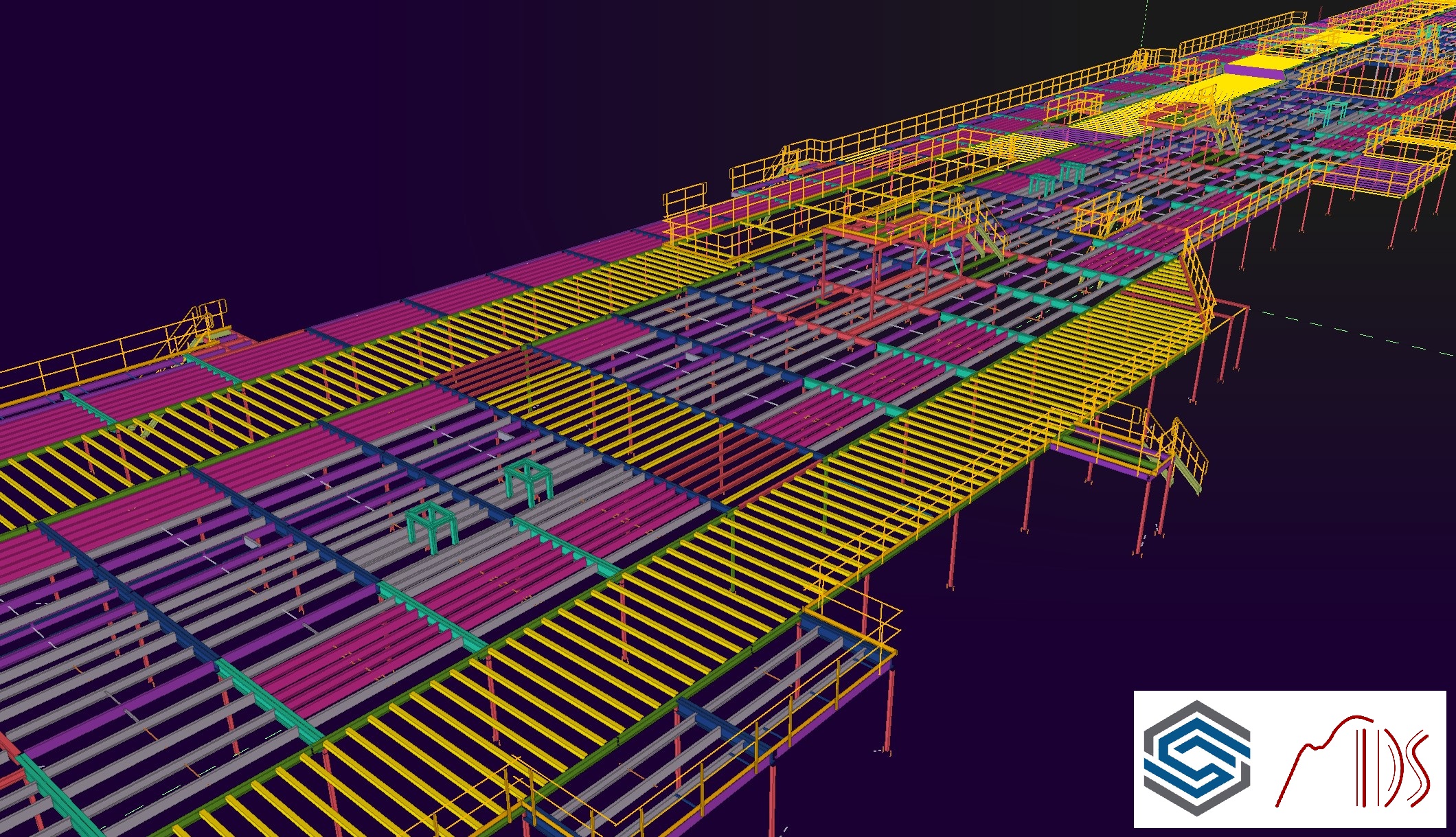
Jedná se o nosné konstrukce pro technologii třídění zavazadel. Důvodem stavby bylo rozšíření kapacit terminálu mezinárodního letiště. Všechny konstrukce se nacházejí v interiéru a navíc pod úrovní terénu. Celý projekt je členěn na tři části – „A“, „Gallery“ a „B“. Část „A“ má hrubé půdorysné rozměry 60 x 208 m a maximální výšku 12 m. Jedná se o mnohoúrovňovou konstrukci nesoucí jak technologii, tak obslužné lávky, schodiště a žebříky. Technologie se různě protíná a mění směr, prakticky se v patrech nad sebou neopakuje. Část „B“ má hrubé půdorysné rozměry 28 x 340 m a maximální výšku 4,5m. Konstrukce je převážně v jedné úrovni s přístupovými schodišti a žebříky. Horní povrch plošiny není vodorovný, ale kopíruje podlahu ve spádu, který na délku 340 m dělá cca 1,7 m výšky. Třetí část „Gallery“ spojuje dvě předcházející a má hrubé rozměry 6,5 x 360 m. Konstrukce je navržena do podzemního tunelu a místy zabírá celou možnou šířku i výšku. Tunel má navíc podlahu v několika spádech, zhruba v polovině je nejvyšší bod a do obou směrů klesá.
Náročnost projektu je patrná již z rozměrů celé konstrukce. Konstrukce přechází přes mnoho objektových dilatací. Dalším aspektem významně komplikující práci je vestavba do již hotového objektu, který má své tolerance, stávající technologie a tvar nebylo možné zaměřit s takovou přesností, jakou by bylo potřebné. Podkladem bylo tedy 3D zaměření objektu – point cloud, běžné geodetické zaměření i hrubé měření a kontrola rozměrů v době montáže. Tyto rozměry museli konstruktéři v průběhu celého projektu neustále kontrolovat a žádat o dopřesnění. Montáž totiž probíhala v částech „A“ a „B“ současně a potom se částí „Gallery“ spojila. Konstruktéři rovněž kontrolovali požadavky světlých výšek a další geometrické zásady technologické části.
Celý proces běžel kontinuálně, tzn. v jedné chvíli se část montovala a jiná část se ještě řešila v principech a zadání. Mimo to přicházely revize zadání (technologie, tvary, kolize s budovou a stávající technologií). Bylo tedy nutno kontrolovat stav revidované části, protože často jedna revize zasáhla do konstrukce, která byla v různé fázi procesu (statika, model, schvalování, výroba, montáž). V průběhu projektování a výstavby bylo evidování přes 100 větších či menších revizí! Tyto aspekty kladly velké nároky na koordinaci mezi jednotlivými účastníky procesu – statiky, konstruktéry, zákazníka, ostatní profese a v neposlední řadě i managementu celé akce a montéry na stavbě, kteří rovněž používali 3D data pro plánování a proveditelnost montáže.
It is an indisputable fact that without the modern tools Tekla Structures Steel Detailing, Tekla Sharing, and Trimble Connect, the whole process could not run at such a pace and with such quality. All resource documents and assignments were handed over in the form of 3D models and data.
These are load-bearing structures for luggage sorting technology. The reason for the construction was to expand the capacity of the international airport terminal. All structures are located in the interior and also below ground level. The whole project is divided into three parts – “A”, “Gallery” and “B”. Part “A” has rough floor plan dimensions of 60 x 208 m and a maximum height of 12 m. It is a multi-level construction carrying both technology and service bridges, stairs, and ladders. The technology intersects in various ways and changes direction, it practically is not the same on the neighboring floors. Part “B” has rough floor plan dimensions of 28 x 340 m and a maximum height of 4.5 m. The structure is mostly at one level with access stairs and ladders. The upper surface of the platform is not horizontal, but it copies the floor in a slope, which makes about 1.7 m of height per 340 m of length. The third part referred to as “Gallery” connects the two previous parts and has gross dimensions of 6.5 x 360 m. The structure is designed for an underground tunnel and in some places occupies the entire possible width and height. In addition, the tunnel has a floor in several slopes, with the highest point approximately in the middle from which it descends in both directions.
The complexity of the project is evident from the dimensions of the entire structure. The structure passes over many object dilatations. Another aspect that significantly complicates the work is the installation in the already finished object, which has its tolerances. The existing technology and shape could not be surveyed with such accuracy as would be necessary. The basis was, therefore, a 3D survey of the building – point cloud, common geodetic survey, and rough measurement and control of dimensions at the time of installation. Designers had to constantly check these dimensions throughout the project and ask for clarification when necessary. The assembly took place in parts “A” and “B” at the same time and then these two parts were interconnected by the “Gallery”. The designers also checked the requirements for clear heights and other geometric principles of the technological part.
The whole process ran continuously, i.e. during the assembly of one part, another part was still subject to discussions/reviews in terms of principles and assignments. Also, there were revisions to the assignment (technology, shapes, collisions with the building, and existing technology). It was, therefore, necessary to check the condition of the revised part, because often one revision affected the structure, which was at different stages of the process (statics, model, approval, production, assembly). During the design and construction, there were over 100 major or minor revisions! These aspects placed great demands on the coordination between the individual participants in the process – structural engineers, designers, the customer, other professions, and, last but not least, the management of the project and installers on-site, who also used 3D data for planning and feasibility of assembly.


Deixe o seu comentário
A Construsoft é revendedor autorizado de Tekla Structures e disponibiliza formação, suporte técnico e outros serviços aos seus clientes.
Para mais informações, visite nosso site:
construsoft.ptTekla is a Trimble Company © Copyright 2026 Tekla