HALA PRODUKCYJNO-MAGAZYNOWA Z BUDYNKIEM BIUROWYM W ZACHODNIOPOMORSKIM

| Category | Industrial Projects |
|---|---|
| Year | 2024 |
| Country | Poland |
| Organization | Pekabex S.A. |
| Author | Pekabex S.A. |
| Place of construction | ZACHODNIOPOMORSKIE |
| Tags | PrefabConcreteTekla Structures |
PROJEKT
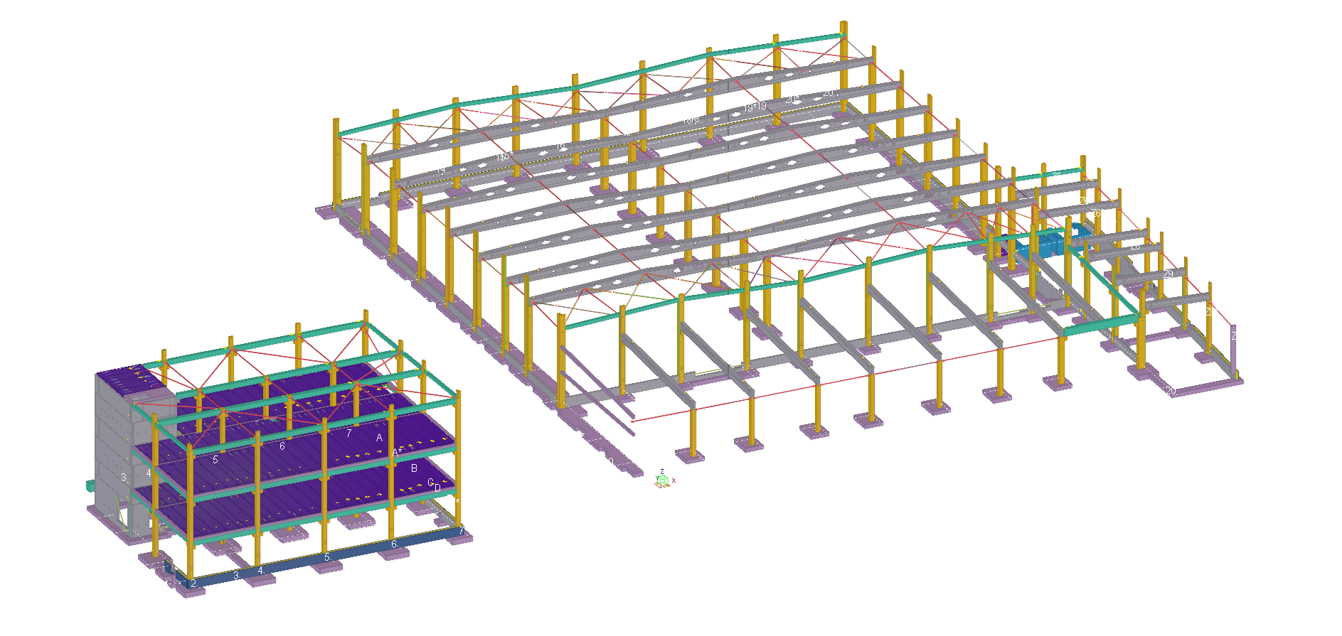
Projekt i koordynacja montażowo-produkcyjna zespołu obiektów dla inwestora – producenta urządzeń grzewczych, powstały w wyjątkowo krótkim czasie 5 tygodni roboczych. Rozbudowa i modernizacja zakładu produkcyjnego objęła: halę magazynowo – produkcyjną o łącznej powierzchni użytkowej 2.551 m², wraz z budynkiem socjalnym o powierzchni użytkowej 1.441 m² i biurowym o powierzchni użytkowej 308 m².
Projekt wyróżnia się pod względem typu konstrukcji – użycie Tekli w przypadku konstrukcji żelbetowej jest dużo rzadsze niż w przypadku konstrukcji stalowej.
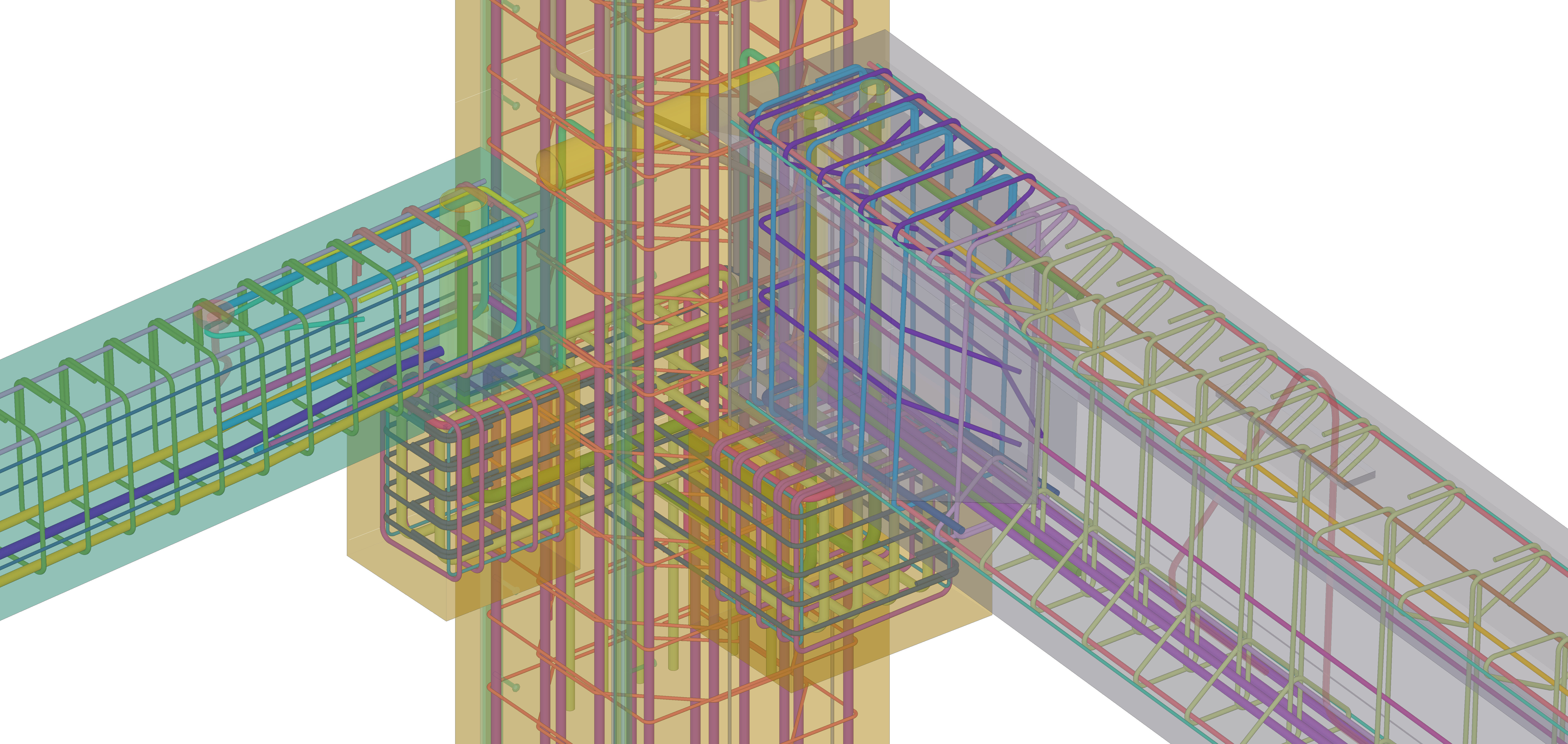
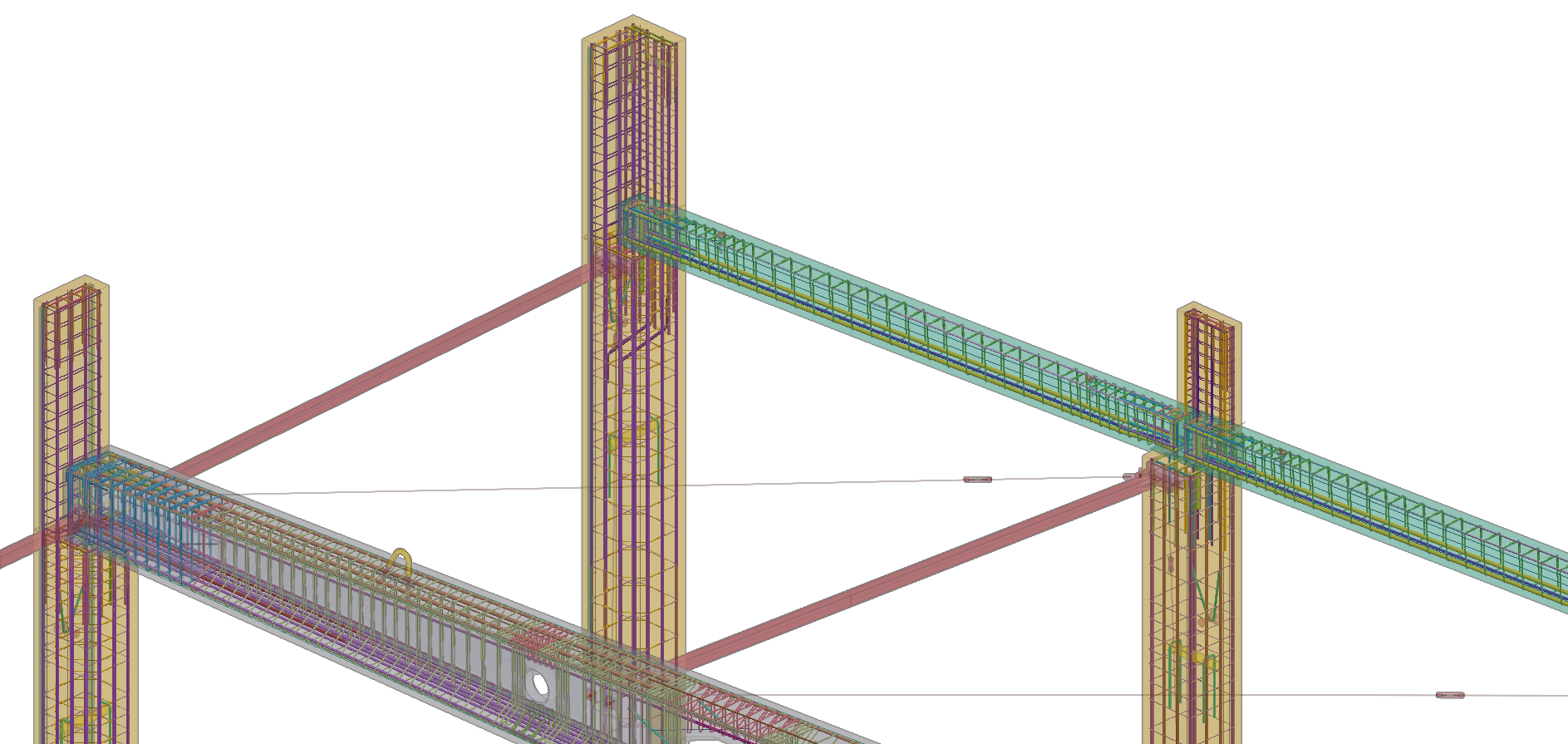
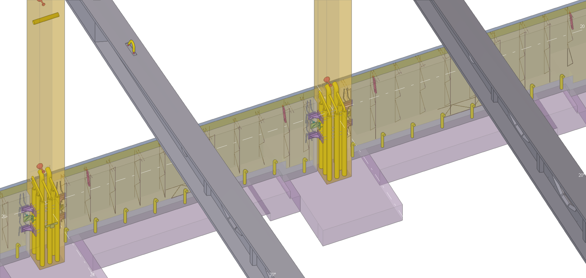
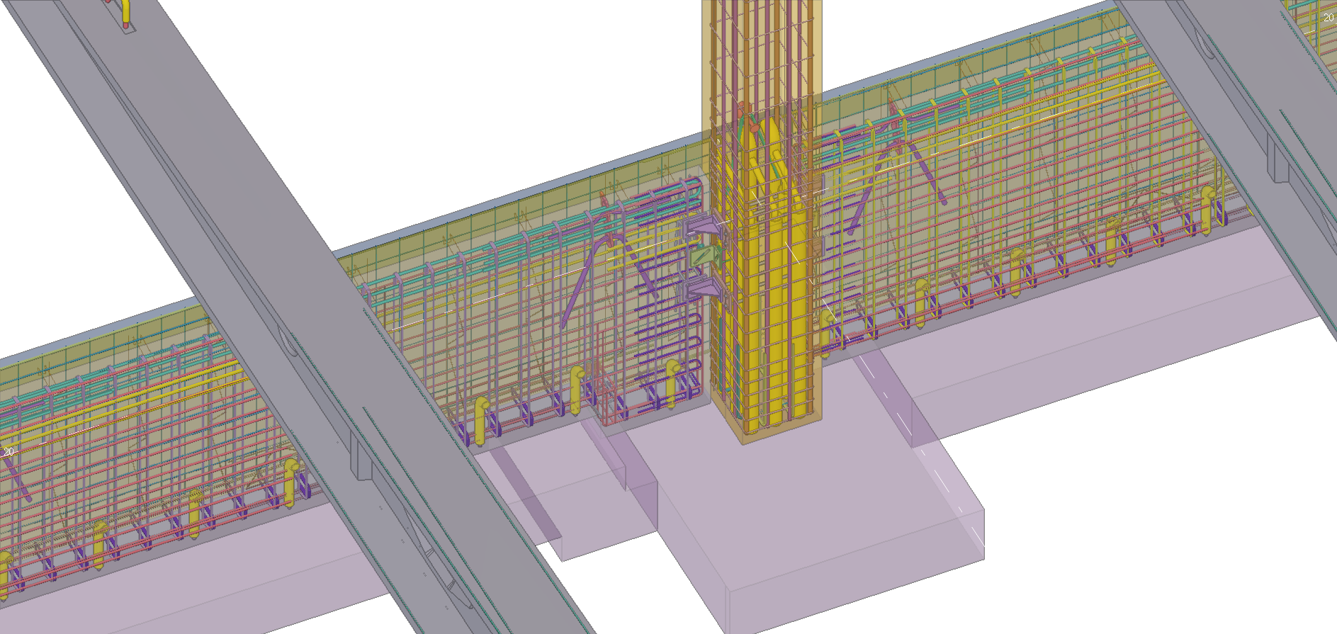
Projekt wykonawczo-warsztatowy obu obiektów oraz projekt warsztatowy stężeń zawierał model 3D, który został wykonany w wysokim poziomie szczegółowości – Level of Development (LOD) 400.
Liczba elementów prefabrykowanych konstrukcji wyniosła: 1282 szt.
Łączna masa prefabrykatów (betonu i stali):1640 t.
Łączna liczba transportów z elementami na budowę: 71 transportów.
HALA PRODUKCYJNO-MAGAZYNOWA dł. 58m x szer. 67m x wys. 10m.
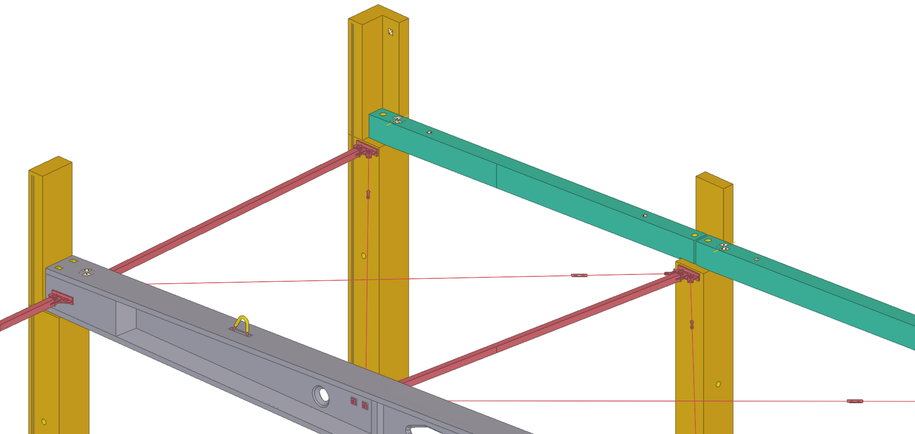
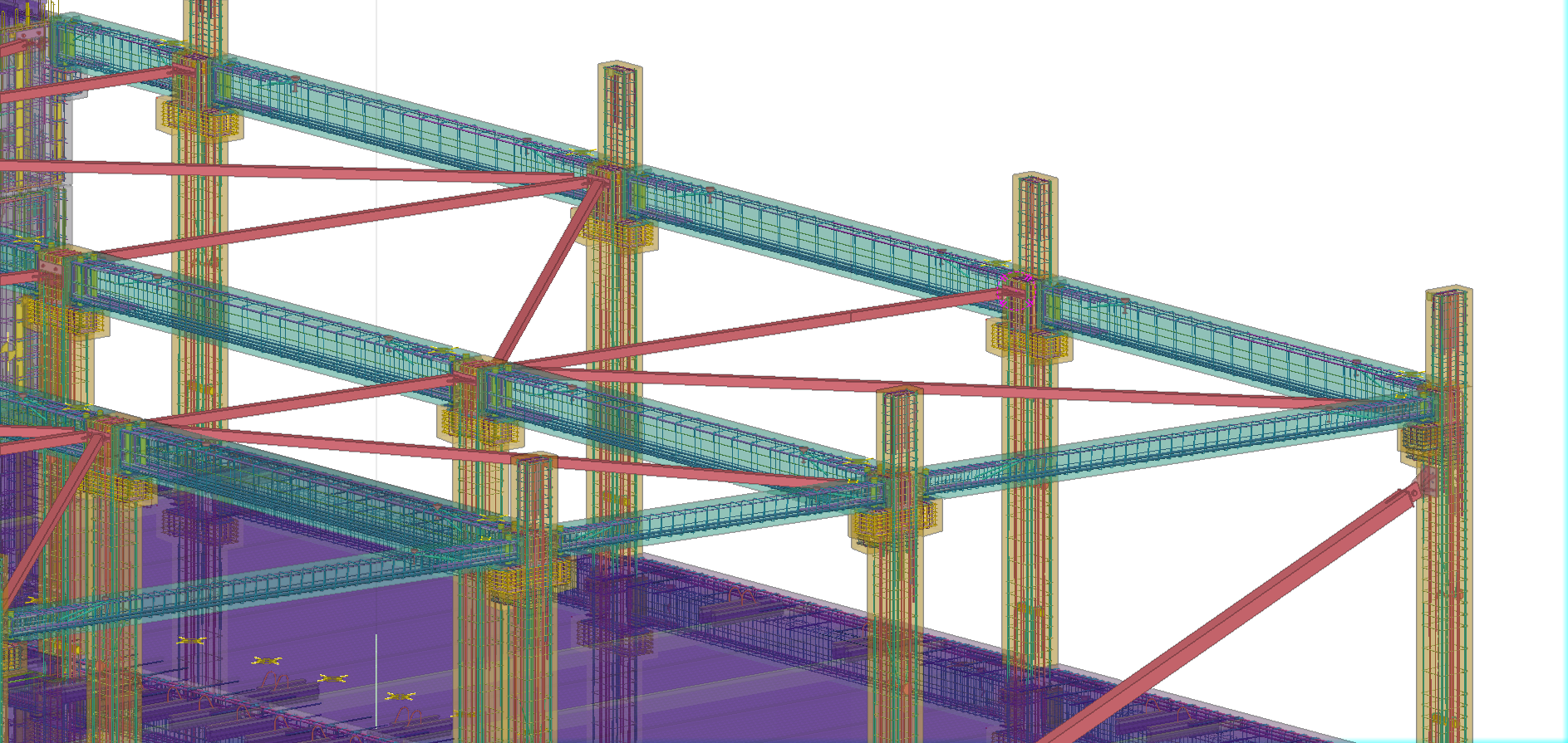
Stateczność konstrukcji prefabrykowanej zapewniona została poprzez utwierdzenie słupów żelbetowych w fundamentach oraz system stalowych stężeń dachowych.
• Słupy żelbetowe z licznymi akcesoriami, wspornikami oraz attykami (59 szt).
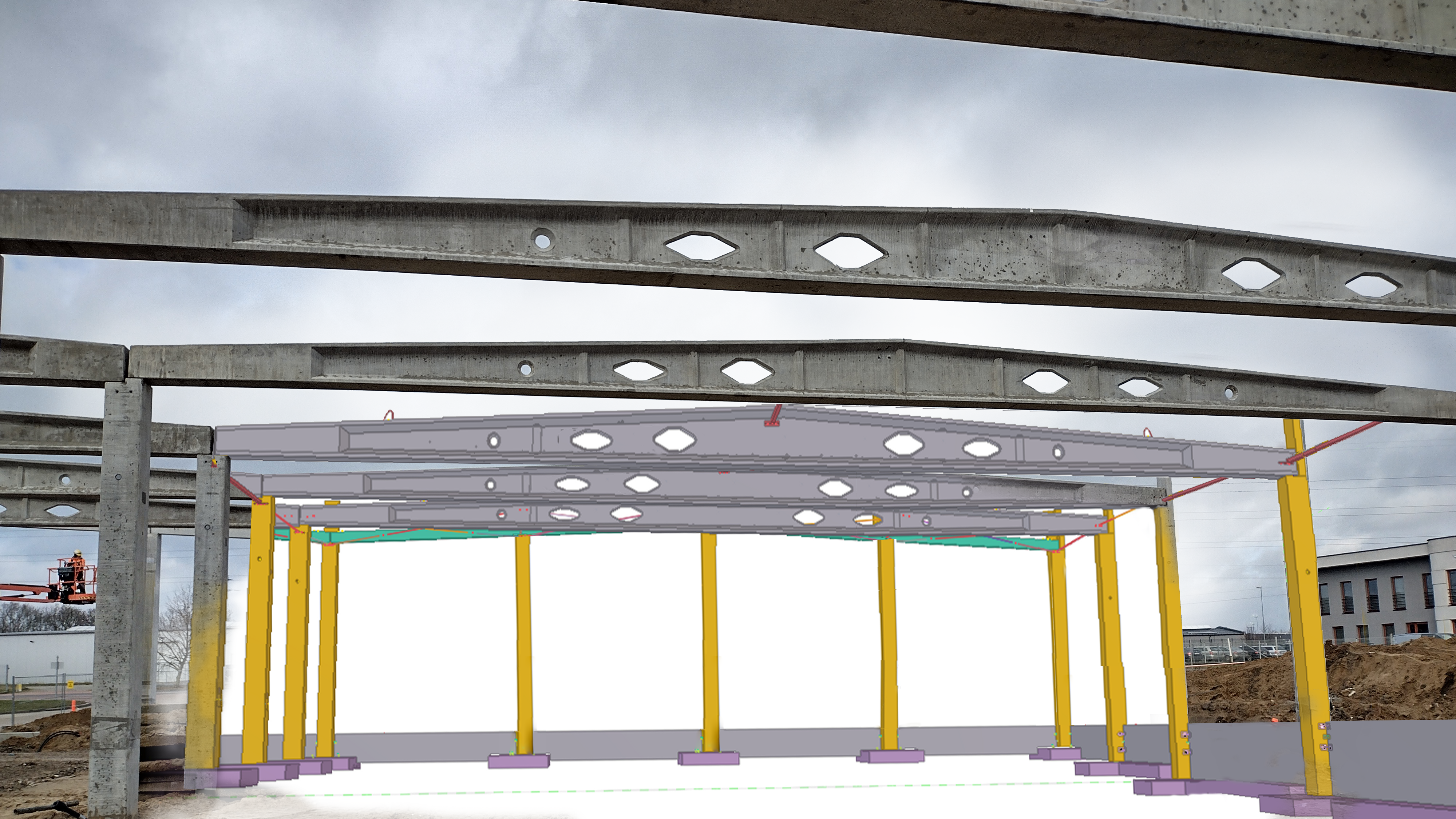
• Strunobetonowe dźwigary dwuspadowe o przekroju poprzecznym dwuteowym z rozbudowanymi blokami końcowymi oraz słupkami usztywniającymi. W środnikach dźwigarów zlokalizowano otwory okrągłe oraz trapezowe (30 szt.)
• Żelbetowe elementy belkowe: niesymetryczny wymian z konsolą boczną (1 szt.) oraz żelbetowe belki w ścianach szczytowych (73 szt.).
• Podwaliny jednowarstwowe (1W): 24 szt. oraz podwaliny trójwarstwowe (3W), które pełnią funkcję ścian oporowych, znajdujące się przy rampie wjazdowej do strefy dostaw: 38 szt.
• Żelbetowe prefabrykowane doki: 2 szt.
CZĘŚĆ SOCJALNO-BIUROWA dł. 27m x szer. 20m x wys. 14m
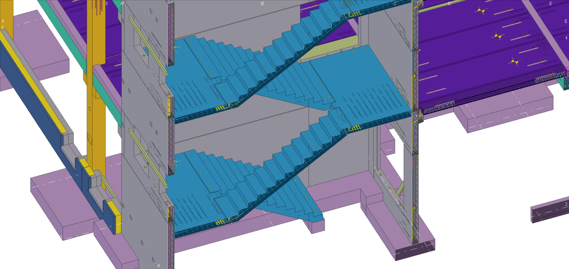
Budynek socjalno-biurowy 3-kondygnacyjny, stateczność konstrukcji zapewnia prefabrykowana żelbetowa klatka schodowa, stalowe stężenia ścienne, stalowe stężenia dachowe oraz stropy z płyt kanałowych. Strunobetonowe belki stropowe kompozytowe, wylewane w dwóch etapach w różnym czasie. Klatka schodowa wykonana w całości z elementów prefabrykowanych, takich jak ściany, biegi i spoczniki.
• Żelbetowe słupy prefabrykowane 3-kondygnacyjne (ciągłe) z konsolami pod belki stropowe oraz z licznymi akcesoriami: 18 szt.
• Ściany: 20 szt.
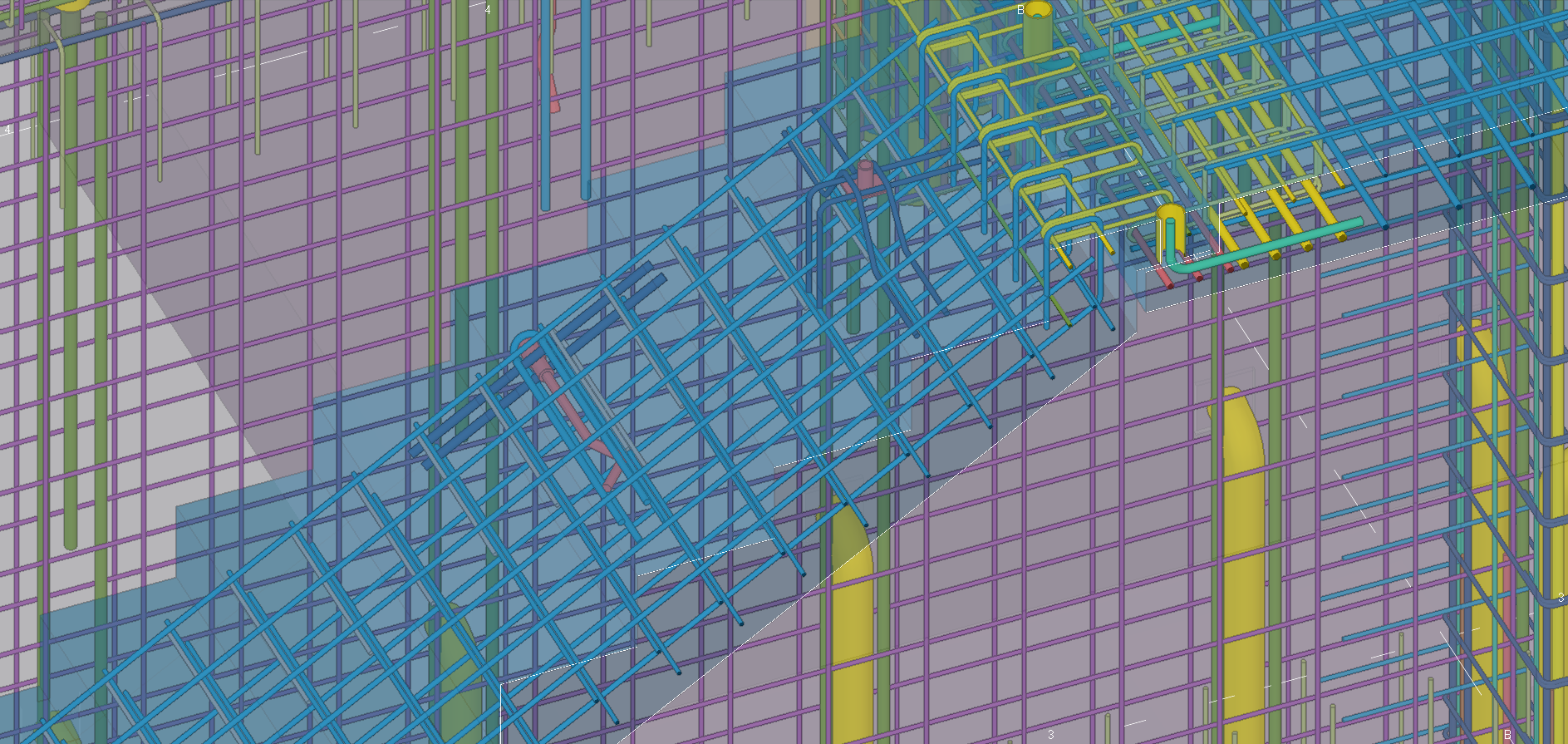
• Biegi schodowe: 4 szt.
• Spoczniki: 4 szt.
• Płyty kanałowe HC200 z licznymi otworami pod instalacje sanitarne i wentylacyjne oraz wymianami stalowymi: ~960m2
• Wymiany stalowe: 8 szt.
ZRÓWNOWAŻONE BUDOWNICTWO
Idea zrównoważonego budownictwa, już od momentu projektowania, to uzupełnienie naszej strategii biznesowej. Nasza misja to zmniejszenie do minimum oddziaływania działalności na środowisko naturalne oraz klimat poprzez dostarczanie najlepszych inżyniersko oraz ekologicznych rozwiązań dla budownictwa. Dlatego pracujemy na elementach konstrukcyjnych, które są certyfikowane dokumentami EPD (Environmental Product Declaration).
Już na etapie pierwszych rozmów z inwestorem o realizacji obiektu, wyliczyliśmy poziom śladu węglowego dla tego typu obiektu na poziomie: 216 704 kg CO2e
WYZWANIA
Wyzwaniem inżynierskim, na etapie pozyskiwania kontraktu oraz podczas projektowania, było spełnienie równocześnie kilku wymogów:
• ograniczenie oddziaływania na sąsiednią halę (worki śnieżne) – dopasowanie wysokości zabudowy projektowanej hali (linia attyk)
• ograniczenie sił na fundamenty wykonywane przy istniejącej hali – fundamenty można było rozbudowywać tylko do wnętrza projektowanej hali – problem z przeniesieniem mimośrodowych sił od słupów
• zapewnienie wymaganego przez inwestora światła hali i powierzchni zabudowy pod regały wysokiego składowania (początkowo wysokość hali wynosiła 15 m)
• odporność ogniowa elementów nośnych oraz elementów stanowiących część ścian oddzielenia pożarowego wyniosła R120
• model 3D został wykonany w wysokim poziomie szczegółowości – Level od Development (LOD) 400
• dwa zespoły projektowe pracujące równolegle na dwóch budynkach z wykorzystaniem usługi Tekla Model Sharing
Dla budynku socjalnego wyzwaniem było zapewnienie stateczności całej konstrukcji nośnej zaprojektowanej w układzie słupowo-belkowym.
• Lokalizacja klatki schodowej w narożniku obiektu wymagała wprowadzenia dodatkowych usztywnień w postaci ścian lub stężeń stalowych. Ograniczała nas jednak mocno architektura obiektu (lekkie ściany działowe bez kontynuacji na kolejnych piętrach) oraz sposób prowadzenia instalacji sanitarnych (w grubości ścian zewnętrznych).
Inne wyzwanie:
• Krótki czas projektowania z koordynacją montażowo-produkcyjną (5 tygodni roboczych) dwóch budynków o bardzo dużym zróżnicowaniu typów elementów – pomogła technologia BIM w koordynacji wielobranżowej, kontroli kolizji, generowaniu dokumentacji branżowej. Termin od momentu zaprezentowania projektu po podpisaniu umowy do wydania na produkcję pierwszych elementów (3 tygodnie robocze).
• Krótki czas montażu (4 tygodnie robocze) równolegle dwóch budynków na zmianę z pracami monolitycznymi kolejnych kondygnacji budynku socjalnego.
TRIMBLE PRODUCTS USED
Tekla Structures & Tekla Model Sharing
THE PROJECT
The design and coordination of assembly and production of the group of buildings for the investor – a producer of heating equipment, were completed in a remarkably short time of 5 working weeks. The expansion and modernisation of the production facility included: a warehouse and production hall with a total usable area of 2,551 m², along with a social building with a usable area of 1,441 m² and an office building with a usable area of 308 m².
The project stands out in terms of the type of the construction. Tekla is used much less frequently in reinforced concrete structures than in steel structures.
The detailed and workshop design of both facilities and the steel bracing workshop design included a 3D model, which was made in high level of detail – Level of Development (LOD) 400.
The number of precast structural elements: 1282pcs.
Total weight of precast elements (concrete and steel): 1640t
Total number of deliveries with elements to the construction site: 71 transports
THE WAREHOUSE AND PRODUCTION HALL (length 58m x width 67m x height 10m)
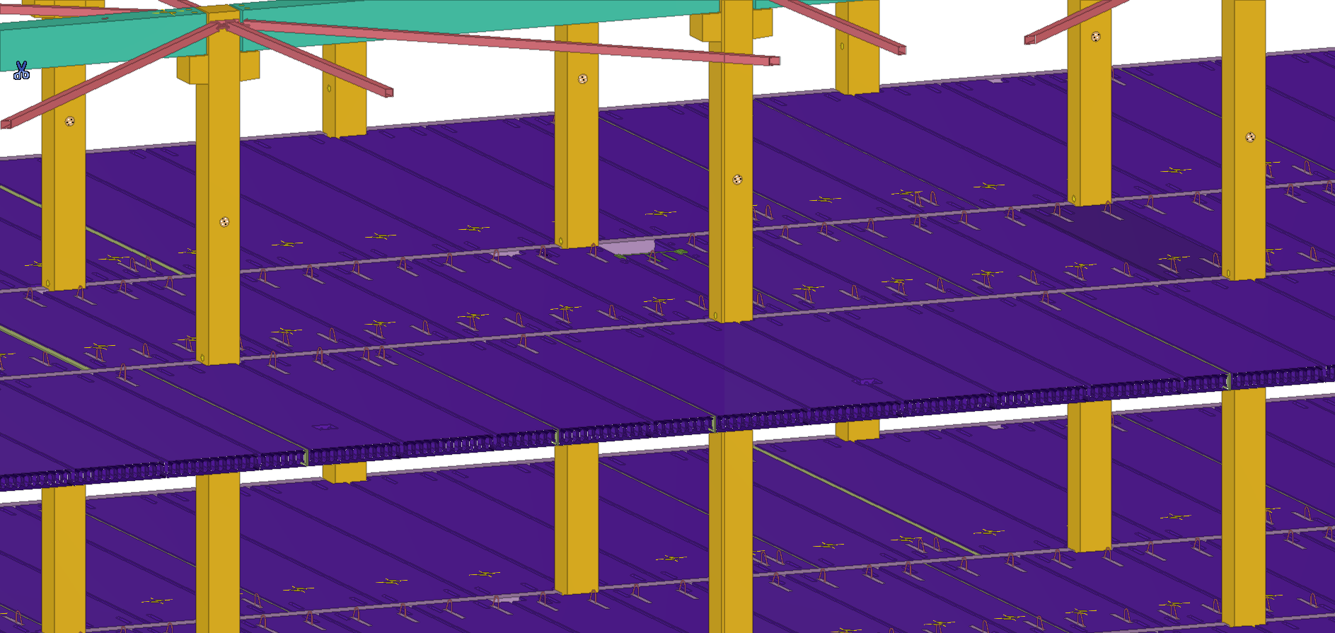
The stability of the precast structure was ensured by restrained column bases and a system of steel bracing at roof level.
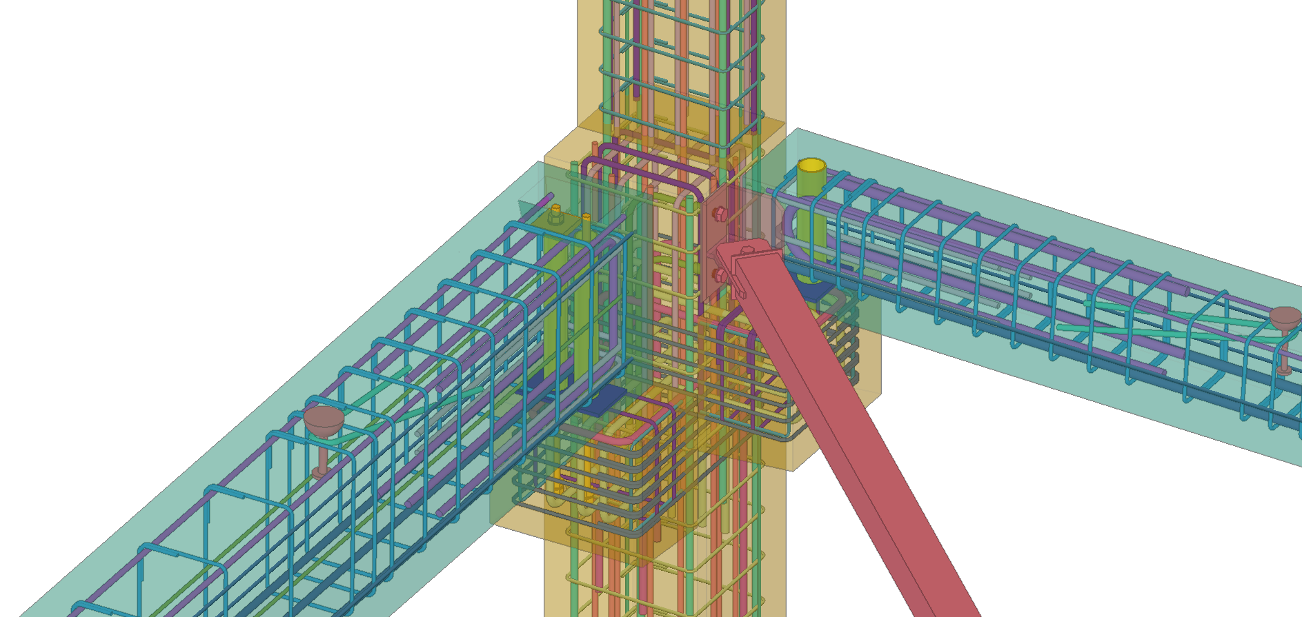
• Precast reinforced concrete columns with numerous accessories, brackets and parapets (59pcs.).
• Precast prestressed girders of I-section with extended end blocks and additional web stiffeners. Round and trapezoidal openings were located in the girder webs. (30 pcs.)
• Precast reinforced concrete beams: an asymmetrical transfer beam with side console (1 pc.) and reinforced concrete beams in the gable walls (73 pcs.).
• Single-layer (1W) socle walls: 24 units and three-layer (3W) socle walls, which act as retaining walls, located at the ramp in the delivery area: 38 pcs.
• Precast reinforced concrete docks (2pcs).
THE SOCIAL AND OFFICE PART (length 27m x width 20m x height 14m)
It is a 3-storey social and office building. Structural stability is ensured by a precast reinforced concrete staircase, system of steel bracing in walls plane, system of steel bracing at roof level and hollow core slab floors. Floor beams were performed as precast prestressed composite floor beams, cast in two stages at different times (the first part cast in the factory, the second part cast on building site). A staircase was made entirely of precast elements such as walls, flights and landings.
• Precast reinforced concrete columns: 3-storey (continuous) columns with corbels for floor beams and numerous accessories: 18 pcs.
• Walls: 20 pcs.
• Stair flights: 4 pcs.
• Stair landings: 4 pcs.
• Hollow core slabs HC200 with numerous openings for sanitary and ventilation installations and steel trimmer beams: ~960m2
• Steel trimmer beams: 8 pcs.
SUSTAINABLE CONSTRUCTION
The idea of sustainable building engineering, right from the very beginning of design, complements our business strategy. Our mission is to minimize the impact of our activities on the natural environment and climate by providing the best engineering and ecological solutions for building engineering. Therefore we use construction elements that are certified by EPD documents (Environmental Product Declaration).
Early on at the stage of the first talks with the investor about the execution of the structure, we calculated the carbon footprint for this type of building at the level of: 216,704 kg CO2e
CHALLENGES
The engineering challenge, at the stage of contract procurement and during the design, was to simultaneously meet several requirements:
• limiting the impact on the adjacent hall (snow drifting) – adjusting the height of the designed hall (altitude of the parapet walls)
• limiting the forces on the foundations casted next to the existing hall – the foundations could only be extended to the interior of the designed hall – problem with transferring eccentric forces from the columns
• providing the space under the construction and building surface area for high storage racks required by the investor (initially, the height of the hall was 15 m)
• fire resistance of load-bearing elements and elements that are part of fire separation walls was R120
• the 3D model was made with a high level of detail – Level of Development (LOD) 400
• two design teams working in parallel on two buildings using the Tekla Model Sharing service
For the social building, the challenge was to ensure the stability of the entire load – bearing structure designed in a column – beam system.
• The location of the staircase in the corner of the building required the implementation of additional stiffeners in the form of walls or steel bracings. However, we were strongly limited by the architecture of the building (light partition walls with no continuation on the upper floors) and the method of routing the sanitary installations (in the thickness of the external walls).
Other challenges:
• Short design time with assembly and production coordination (5 working weeks) of two buildings with a very high diversity of element types – BIM technology helped in multi-discipline coordination, collision control, and generation of technical documentation. The deadline from the moment of presenting the project after signing the contract to the production of the first elements (3 working weeks).
• Short assembly time (4 working weeks) of two buildings in parallel, alternating with monolithic works of the next floors of the social building.
TRIMBLE PRODUCTS USED
Tekla Structures & Tekla Model Sharing

Leave your comment
Construsoft is an authorized Tekla Structures vendor and provides training, technical support, and other services to its customers.
For more information, please visit our website:
construsoft.comTekla is a Trimble Company © Copyright 2026 Tekla