HALA KADŁUBOWA W GDYNI
| Kategoria | Projekty przemysłowe |
|---|---|
| Rok | 2025 |
| Kraj | Poland |
| Organizacja | SWP CONSTRUCTION Sp. z o.o. Sp.k. |
| Autor | SWP CONSTRUCTION |
| Miejsce budowy | GDYNIA |
| Tags | Tekla Structures |
Opracowanie obejmuje propozycję zmian układu konstrukcji stalowej w stosunku do projektu technicznego zadania projektowego jakim jest: „Budowa obiektów kubaturowych: Hali kadłubowej i hali produkcyjnej z budynkiem socjalno- administracyjnym wraz z zagospodarowaniem terenu, rozbudową i przebudową nabrzeża, placów składowych i dróg wewnętrznych wraz z budową, przebudową i likwidacją infrastruktury technicznej towarzyszącej oraz rozbiórką istniejących zadaszeń.”
Propozycja zmian konstrukcji stalowej Hali Kadłubowej stanowi podstawę do oficjalnego zatwierdzenia koncepcji zmian, a w dalszym kroku do rozpoczęcia prac związanych wykonaniem Projektu Wykonawczego oraz Warsztatowego Konstrukcji
Zakres opracowania:
Niniejszy Projekt zmian konstrukcji stalowej Hali Kadłubowej w swym zakresie obejmuje:
– konstrukcję stalową zadaszenia: dźwigary główne, tężniki, stężenia połaciowe i pionowe
– konstrukcję stalową ścian hali w tym: słupy kratowe dolne, słupy kratowe górne, słupy pośrednie, stężenia ścienne pionowe, stężenia ścienne poziomie
– propozycję połączenia i zakotwienia konstrukcji stalowej do fundamentów
– wytyczne łączenia i układania blachy trapezowej
Wykorzystane oprogramowania:
-RFEM
– model 3D konstrukcji w Tekla Structures
Szczegóły konstrukcji:
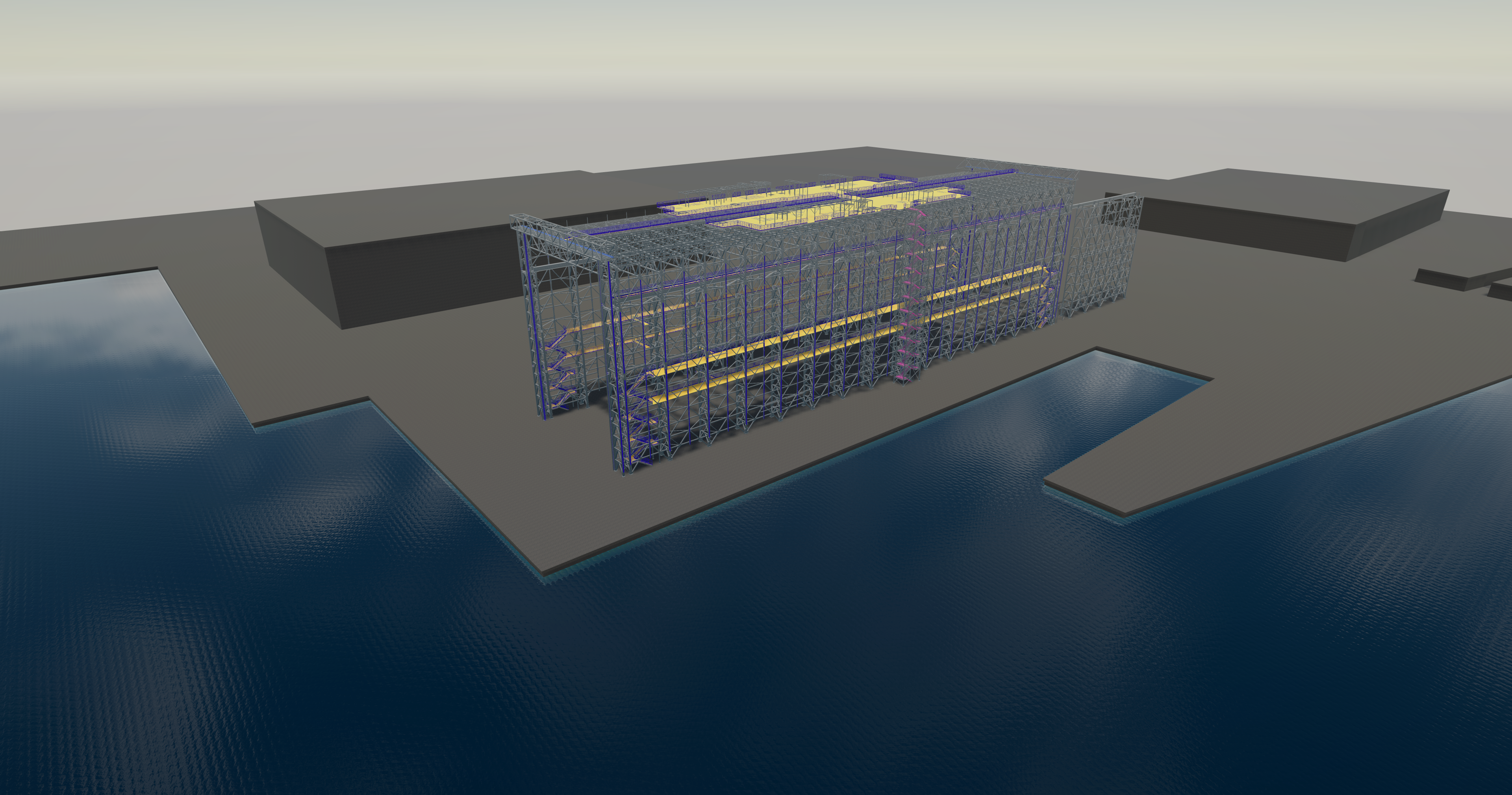
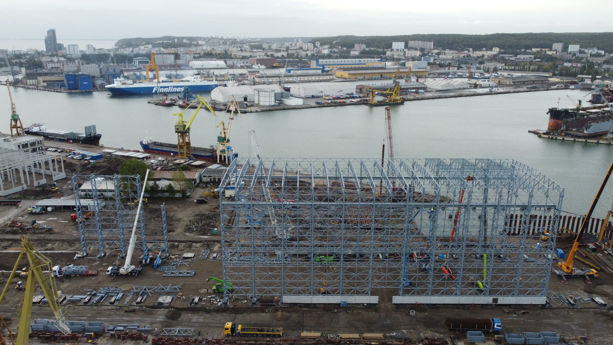
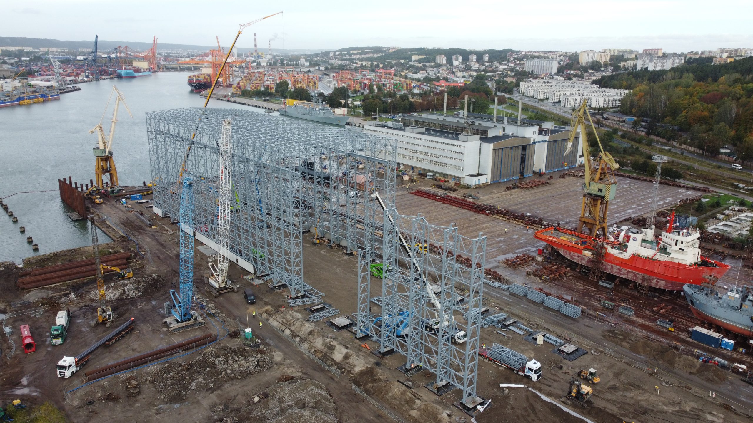
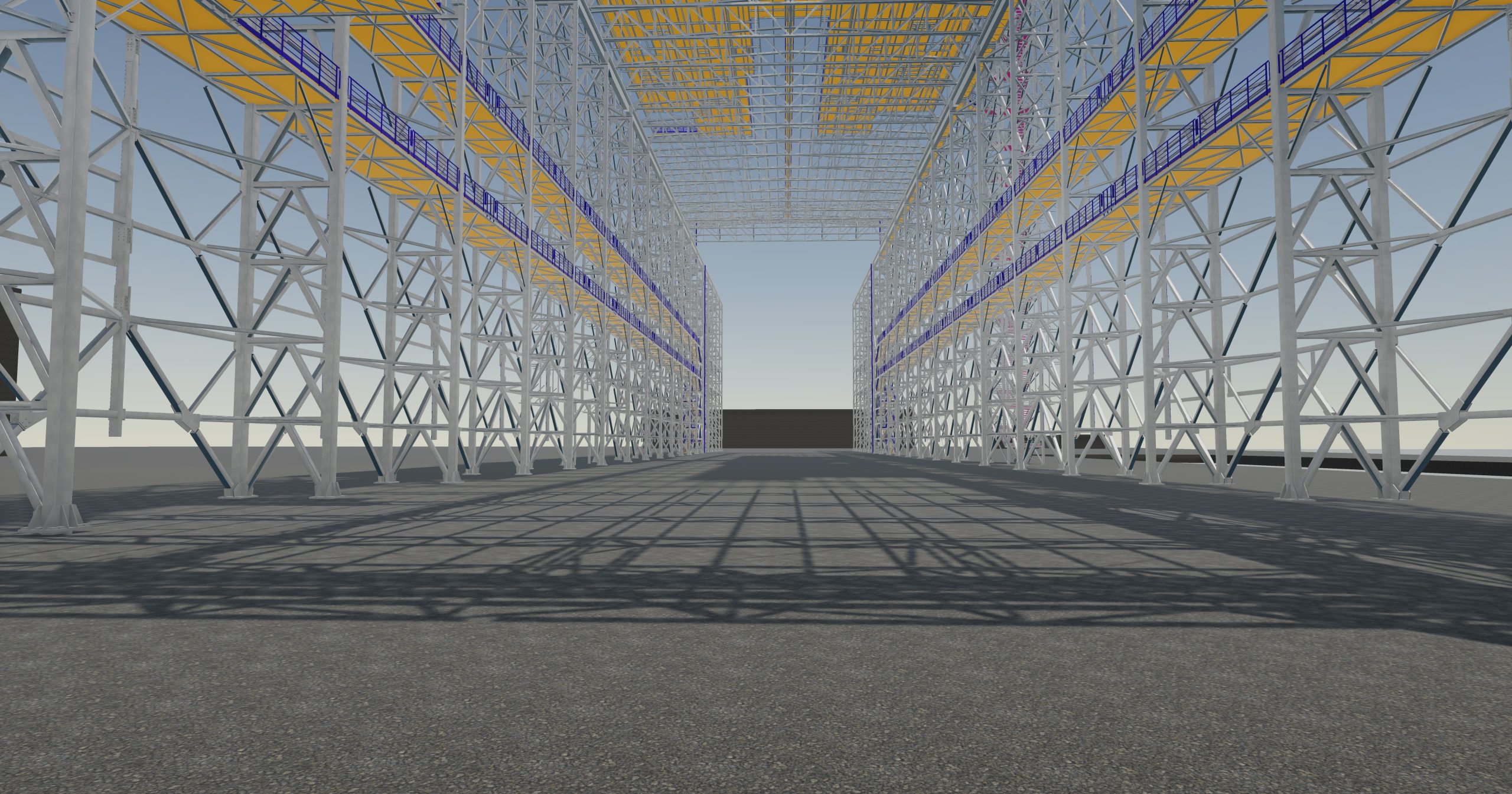
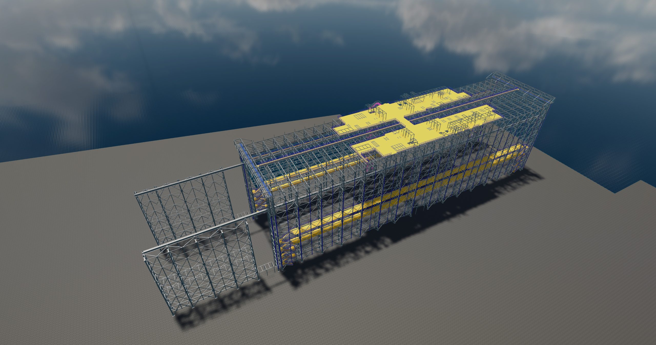
Projektowana Hala Kadłubowa o wymiarach ~154m długości, 38.5m szerokości oraz ~43m wysokości w kalenicy. W części wschodniej dodatkowa estakada zewnętrzna złożona ze słupów kratowych oraz belki podsuwnicowej. Możliwa dalsza rozbudowa Hali Kadłubowej poprzez wykonanie dodatkowych dźwigarów łączonych do słupów estakady oraz pełnego zadaszenia obiektu.
Hala wyposażona w 3 suwnice natorowe, z możliwością jednoczesnego poruszania się po całej długości hali oraz estakady zewnętrznej.
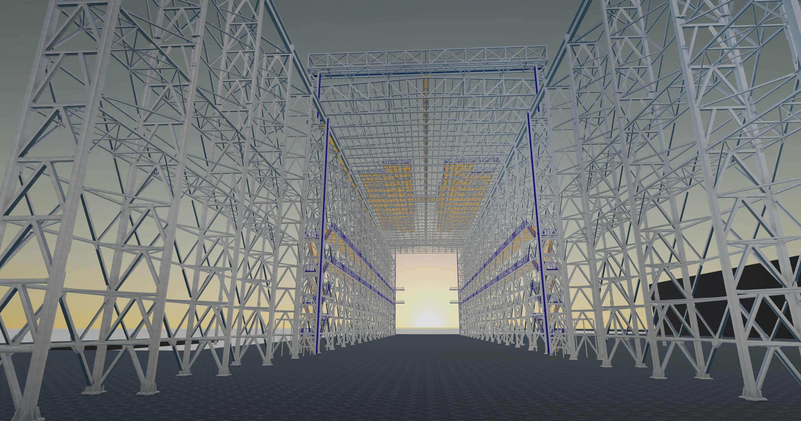
Na obu „czołach” hali bramy mechaniczne – brama wschodnia uwzględniająca możliwość swobodnego przejazdu suwnicy. Brama zachodnia o wymiarach umożliwiających swobodne wprowadzanie poszczególnych sekcji jednostek pływających ich wodowania. Na ścianie północnej brama o wymiarach ok 5x5m.
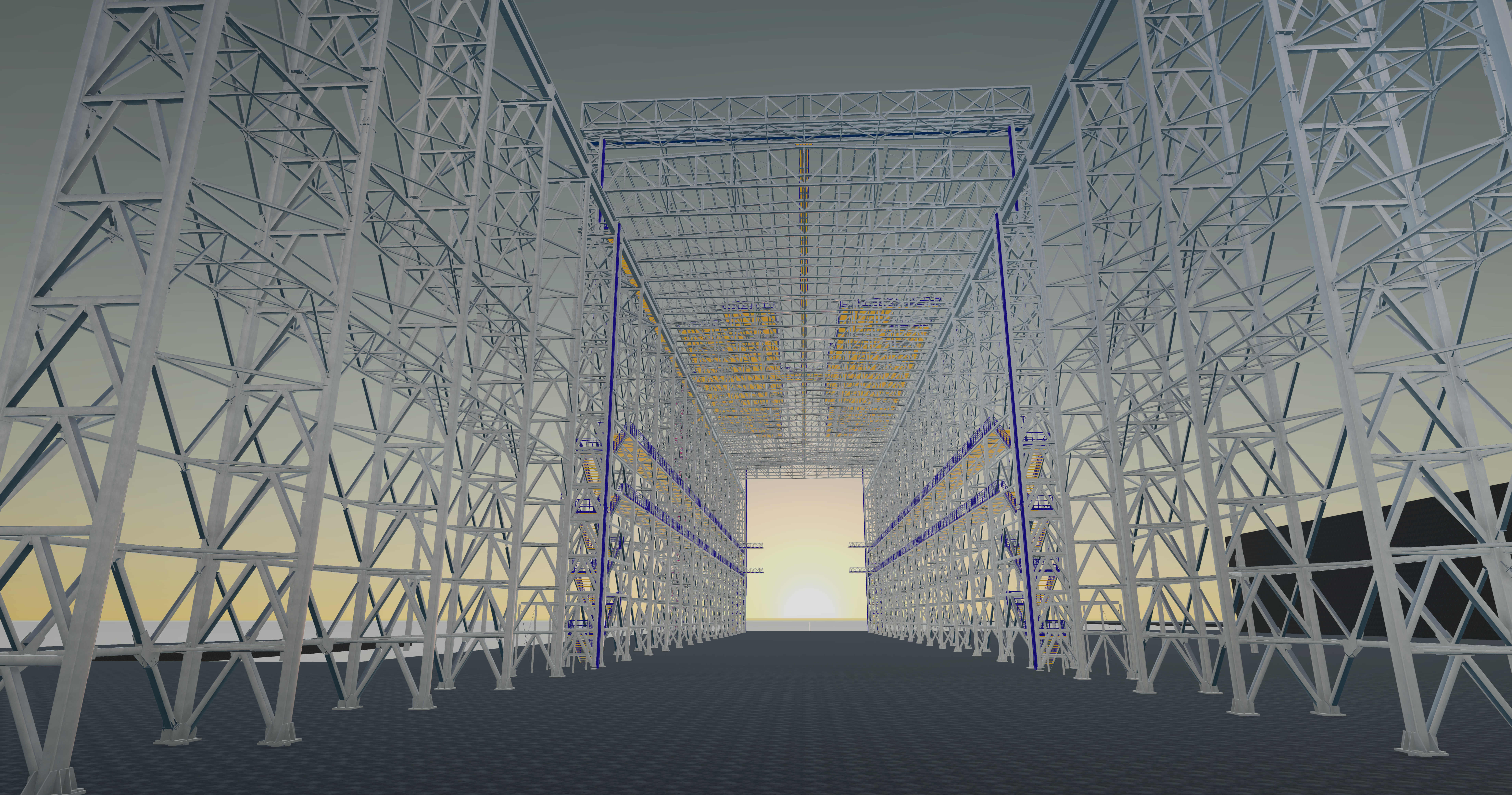
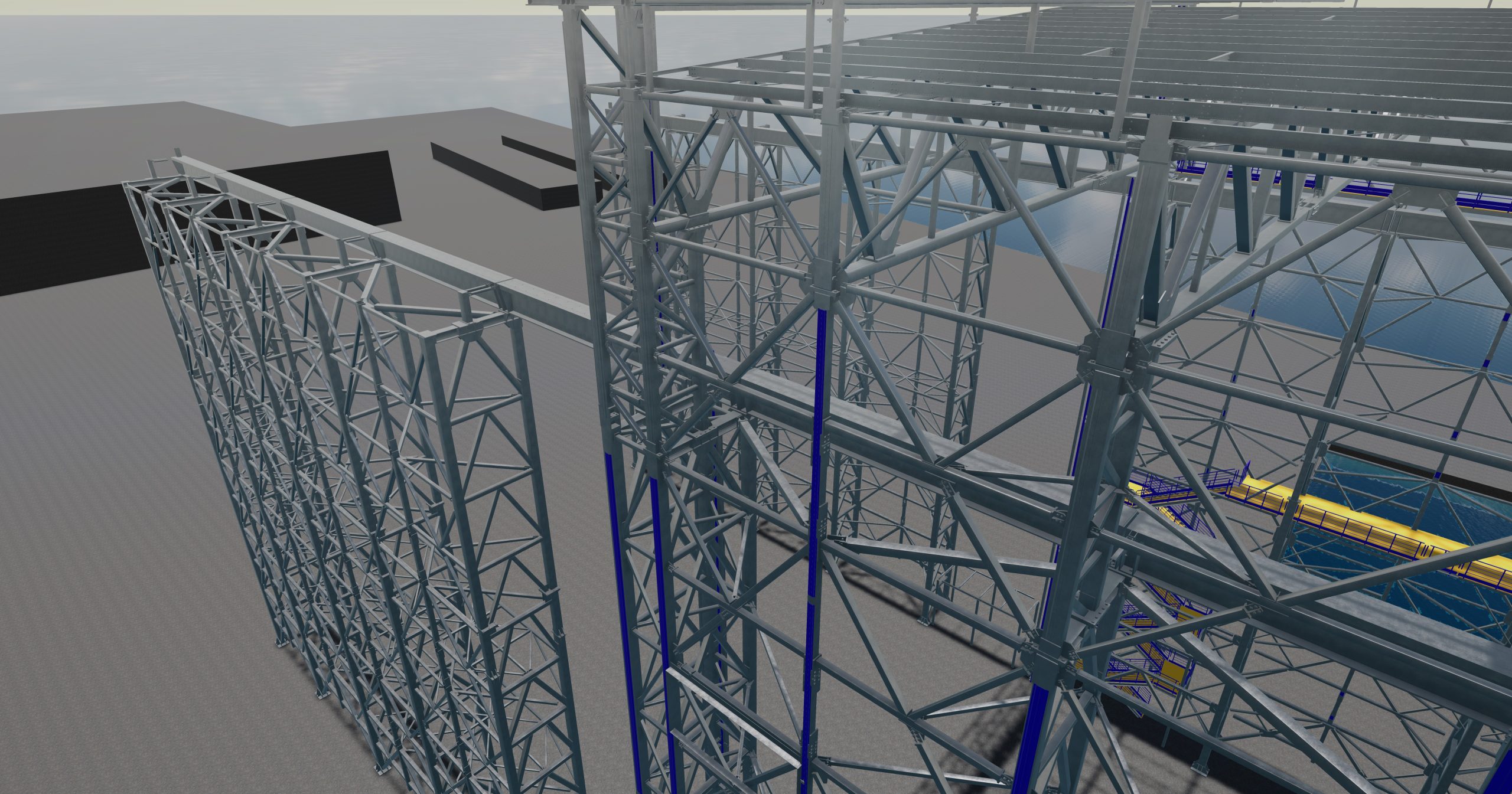
Konstrukcja główna hali złożona z kratowych słupów oraz dźwigarów nośnych. Słupy kratowe główne w rozstawie co 10m, w rejonie osi 8-9 rozstaw 10.9m. W okolicy bramy słupy w rozstawie 9.3m. Dźwigary kratowe o wysokości pasów 3680mm w rozstawie osiowym co 4.65 – 5.45m. Co drugi dźwigar wsparty przez podkonstrukcję stężającą ścian, przekazującą obciążenia bezpośrednio na słupy kratowe. Rozpiętość dźwigarów to ok 37.4m (w osiach zewnętrznych). Nad belką suwnicową słupy o konstrukcji kratowej jednak ze zredukowaną odległością pomiędzy pasami głównymi. Słupy kształtowane w taki sposób alby możliwe było kształtowanie pomostu roboczego suwnicy.
W polach pośrednich pomiędzy słupami głównymi dodatkowe słupy pośrednie. Słupy projektowane jako wsparte na układzie stężeń ściennych. Brak konieczności kształtowania osobnego fundamentu na słupy pośrednie – niezbędne jednak blokowanie boczne, poziome, ze względu na oddziaływanie wiatru. Podpory poziome do realizacji za pomocą np. belki podwalinowej opartej na fundamentach słupów głównych.
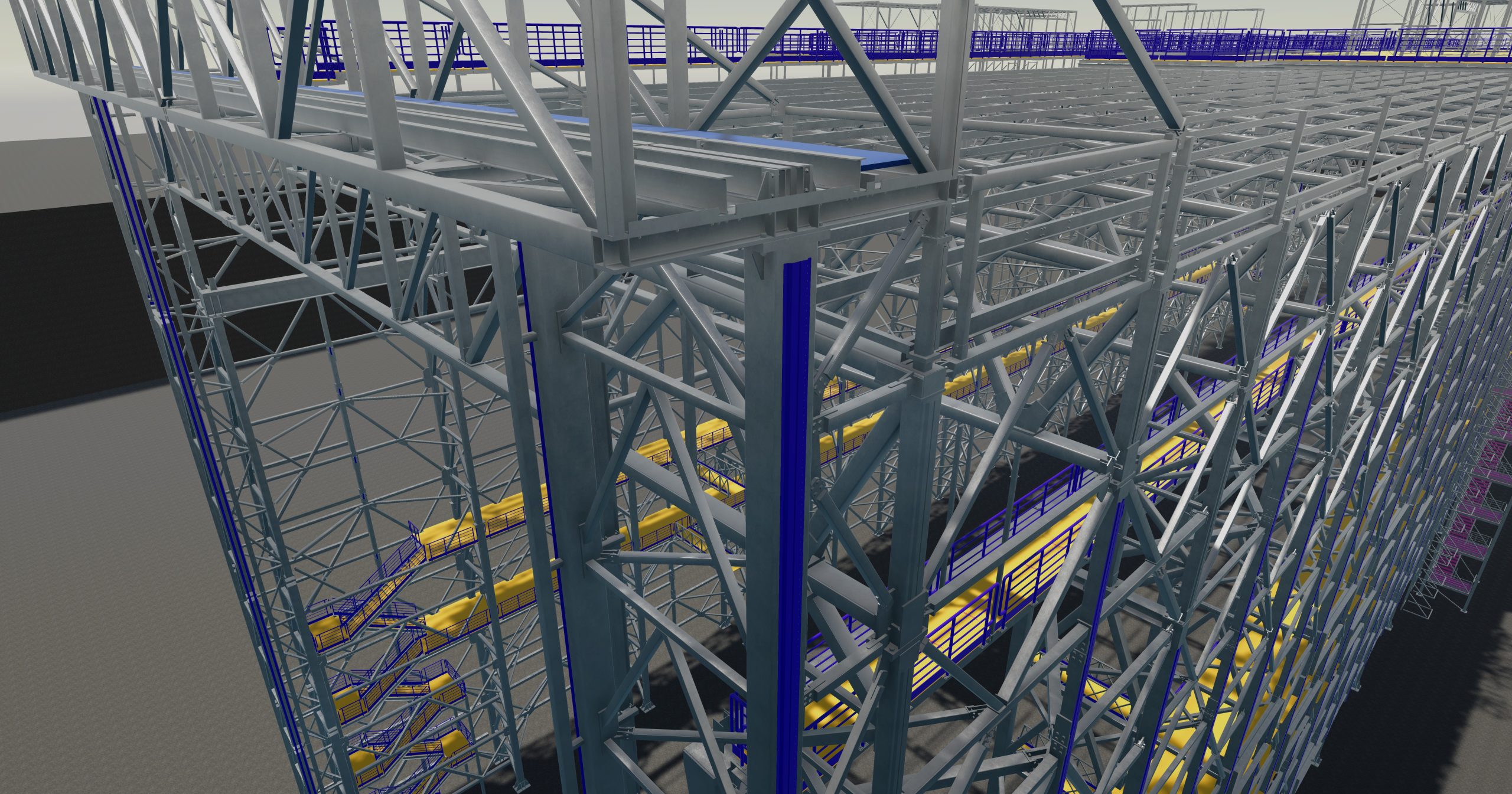
Konstrukcja dachu bezpłatwiowa – blacha trapezowa samonośna o schemacie statycznym belki ciągłej (niezbędne uciąglenie blachy w układzie mijankowym – długość zakładu ok 50-60cm). Blacha trapezowa zdolna do przeniesienia wszystkich oddziałujących bezpośrednio na nią obciążeń. Blacha w żadnym momencie pracy konstrukcji nie stanowi podparcia bocznego pasa górnego dźwigarów kratowych. Stabilizacja konstrukcji odbywa się każdorazowo za pomocą dedykowanej podkonstrukcji nośnej. Pas górny stabilizowany co ok. 6.2m za pomocą tężników połaciowych.
Na poziomach +13.48 oraz + 19.08 dodatkowe pomosty robocze oparte na poziomych wiatrownicach ściennych. Pomosty niezbędne do prawidłowej komunikacji, umożliwiającej budowę jednostki pływającej. Wejście na podesty za pomocą wewnętrznych klatek schodowych, zlokalizowanych w narożnikach hali. W części południowej w bezpośrednim sąsiedztwie suwnicy dodatkowy pomost roboczy jako komunikacja z mostem suwnicy oraz jako element dostępowy do jej bezpośredniej konserwacji. Na dachu przewiduje się wykonanie dużego pod względem powierzchni pomostu roboczego, połączonego bezpośrednio z konstrukcją dachową. Należy bezwzględnie ograniczyć liczbę punktów podparcia pomostu roboczego na dachu w celu redukcji miejsc przebić pionowych elementów podpierających przez poszycie dachowe, które w miejscach przebić wymaga znacznych nakładów pracy w celu wykształtowania stosownego uszczelnienia przebić. Większa liczba przebić dachowych znacząco podnosi ryzyko rozszczelnienia poszycia i wystąpienia usterki, która może wpływać na użytkowanie budynku.
Konstrukcja stalowa posadowiona na palach za pomocą stosownie kształtowanych oczepów żelbetowych. Pomiędzy oczepami belki podwalinowe. Konstrukcja kotwiona za pomocą kotew stalowych wstępnie sprężonych, wykonanych z prętów max M36 (DIN 975/976) klasy 10.9. Zestaw kotwiący złożony z kotew stalowych oraz adaptera łączącego konstrukcję z fundamentem, zdolny do przeniesienia siły wyrywającej rzędu 3.5 MN. Na poziomie ±0.00 posadzka betonowa oraz podbudowa gruntowa zdolna do przeniesienia obciążeń rzędu 200 kN/m2.
Nie przewiduje się potrzeby wykonania dylatacji w budynku hali kadłubowej. Wykonanie dylatacji pełnej budynku obarczone jest znaczącym ryzykiem wykonawczym pod względem konieczności wykonania bardzo dokładnego uszczelnienia budynku, które na etapie użytkowania obiektu może i tak być niewystarczające, z powodu oddziaływania różnych czynników, niezależnych od Projektanta Konstrukcji czy też Generalnego Wykonawcy. W ogólnym założeniu dylatacje budynku halowego przewiduje się, w celu przeciwdziałania wpływowi temperatury – wówczas konstrukcję dzieli się przerwami dylatacyjnymi.
W przypadku rozpatrywanej Hali Kadłubowej jej długość wynosi ok 154m, a stężenia w niniejszej propozycji zmian układu konstrukcyjnego rozstawione są niezwykle gęsto. Dodatkowo obliczenia statyczne przewidują uwzględnienie oddziaływania klimatycznego w postaci równomiernego ogrzania oraz ochłodzenia konstrukcji stalowej. Wobec powyższego propozycja zmian konstrukcji stalowej przewiduje rezygnację dylatacji w osiach 8 – 9 przedłożonej w projekcie technicznym.
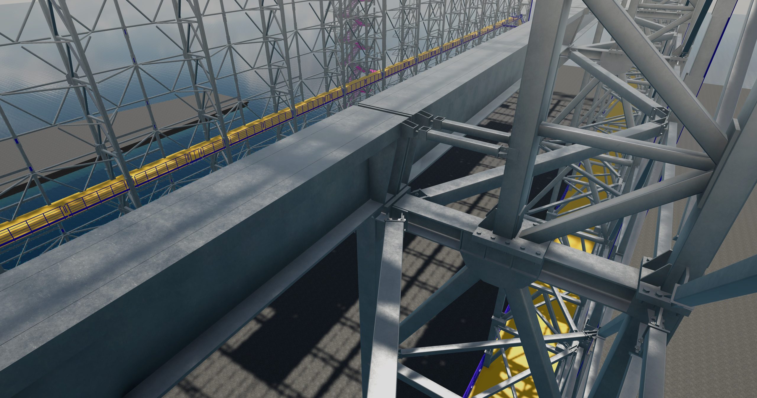
Belka podsuwnicowa wykonana z prefabrykowanej belki sprężonej, żelbetowej zapewniająca dobrą pracę statyczną ze względu na dynamiczne oddziaływanie suwnic. Belka zdolna do przeniesienia stosownych sił poprzecznych w obu kierunkach, momentu skręcającego oraz momentu zginającego w płaszczyźnie mocnej i słabej.
Na ścianie południowej na zewnątrz hali klatka schodowa stalowa, niezbędna do komunikacji pomiędzy poziomem gruntu a poziomem pomostu technicznego na dachu. Klatka lokalnie może być połączona z główną konstrukcją hali w celu stabilizacji oraz redukcji przemieszczeń poziomych. Klatka otwarta, nieobudowana.
The study includes a proposal for changes to the steel structure layout in relation to the technical design of the design task, which is: „Construction of cubic capacity objects: a hull hall and a production hall with a social and administrative building, together with the development of the area, expansion and reconstruction of the quay, storage yards and internal roads, together with the construction, reconstruction and liquidation of the accompanying technical infrastructure and the demolition of the existing roofs.”
The proposed changes to the steel structure of the Hull Hall constitute the basis for the official approval of the change concept and, in a further step, for the commencement of work related to the execution of the Executive Design and Workshop Design of the Structure.
Scope of the study:
This Project of changes to the steel structure of the Hull Hall includes:
– steel structure of the roof: main girders, braces, roof and vertical bracing
– steel structure of the hall walls, including: lower lattice columns, upper lattice columns, intermediate columns, vertical wall bracings, horizontal wall bracings
– proposal for connecting and anchoring the steel structure to the foundations
– guidelines for connecting and arranging trapezoidal sheets
Software used:
-RFEM
– 3D model of the structure in Tekla Structures
Construction details:
The designed Hull Hall with dimensions of ~154m in length, 38.5m in width and ~43m in height at the ridge. In the eastern part, an additional external viaduct consisting of lattice columns and a crane beam. Further expansion of the Hull Hall is possible by making additional girders connected to the viaduct columns and full roofing of the facility.
The hall is equipped with 3 overhead cranes, with the possibility of simultaneous movement along the entire length of the hall and the external viaduct.
Mechanical gates on both „fronts” of the hall – the eastern gate allows for the free passage of the crane. The western gate with dimensions enabling free entry of individual sections of floating units and their launching. On the northern wall, a gate measuring approx. 5x5m.
The main structure of the hall consists of lattice columns and load-bearing girders. Main lattice columns spaced every 10m, in the area of axes 8-9 spaced 10.9m. In the area of the gate, columns spaced 9.3m. Lattice girders with a belt height of 3680mm in an axial spacing of 4.65 – 5.45m. Every second girder supported by a bracing substructure of the walls, transferring loads directly to the lattice columns. The span of the girders is approx. 37.4m (in the external axes). Above the crane beam, columns with a lattice structure, but with a reduced distance between the main belts. Columns shaped in such a way that it is possible to shape the working platform of the crane.
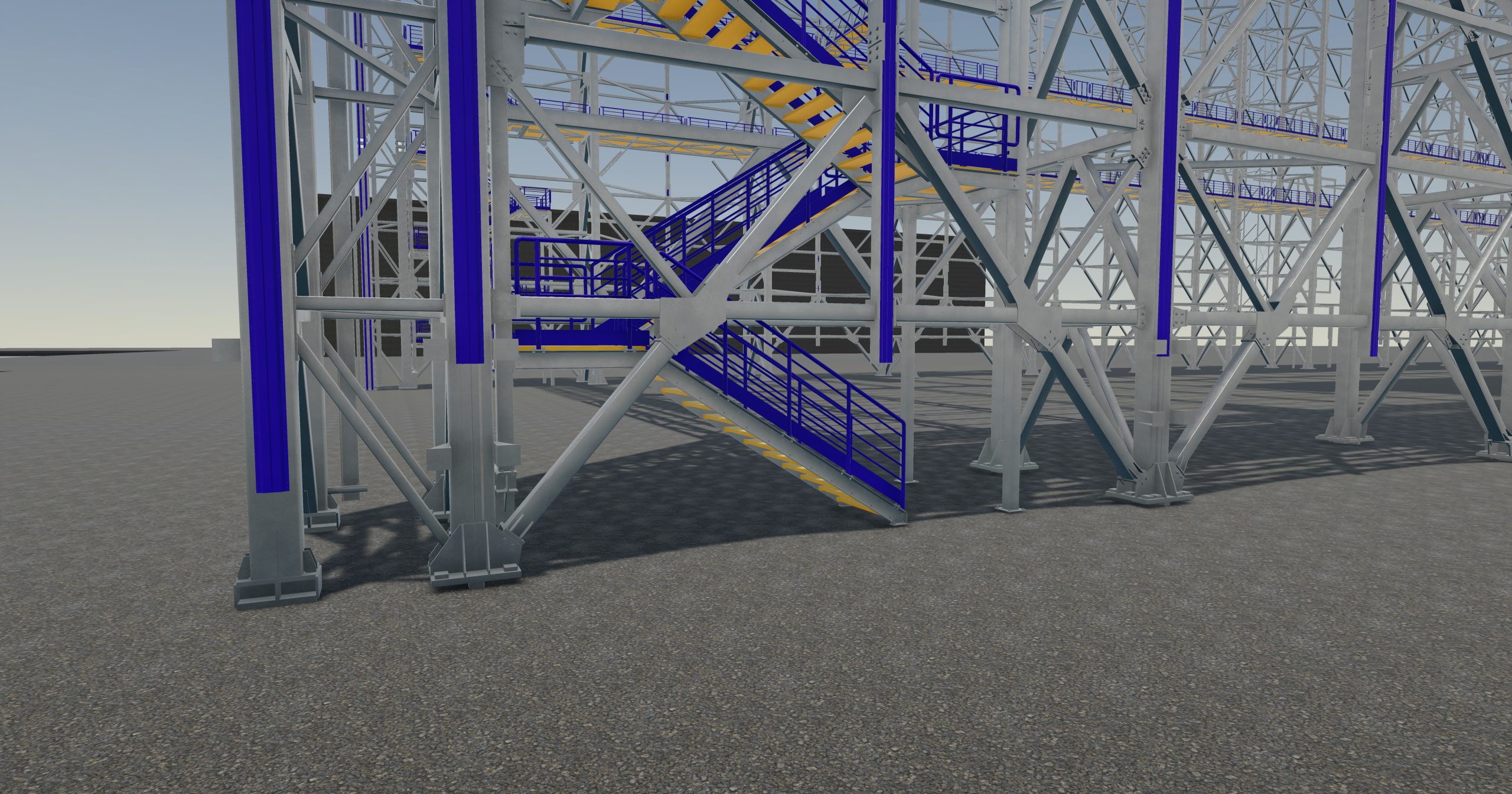
In the intermediate fields between the main columns, additional intermediate columns. Columns designed as supported on a system of wall braces. There is no need to shape a separate foundation for the intermediate posts – however, lateral, horizontal blocking is necessary due to the effect of wind.
Horizontal supports to be implemented using e.g. a ground beam based on the foundations of the main columns.
Roof structure without purlins – self-supporting trapezoidal sheet metal with a static scheme of a continuous beam (it is necessary to continue the sheet metal in a staggered arrangement – overlap length approx. 50-60 cm). Trapezoidal sheet metal capable of transferring all loads acting directly on it. At no point during the operation of the structure does the sheet metal constitute lateral support of the upper chord of the lattice girders. Stabilization of the structure is carried out each time using a dedicated supporting substructure. The upper chord is stabilized approx. every 6.2 m using roof braces.
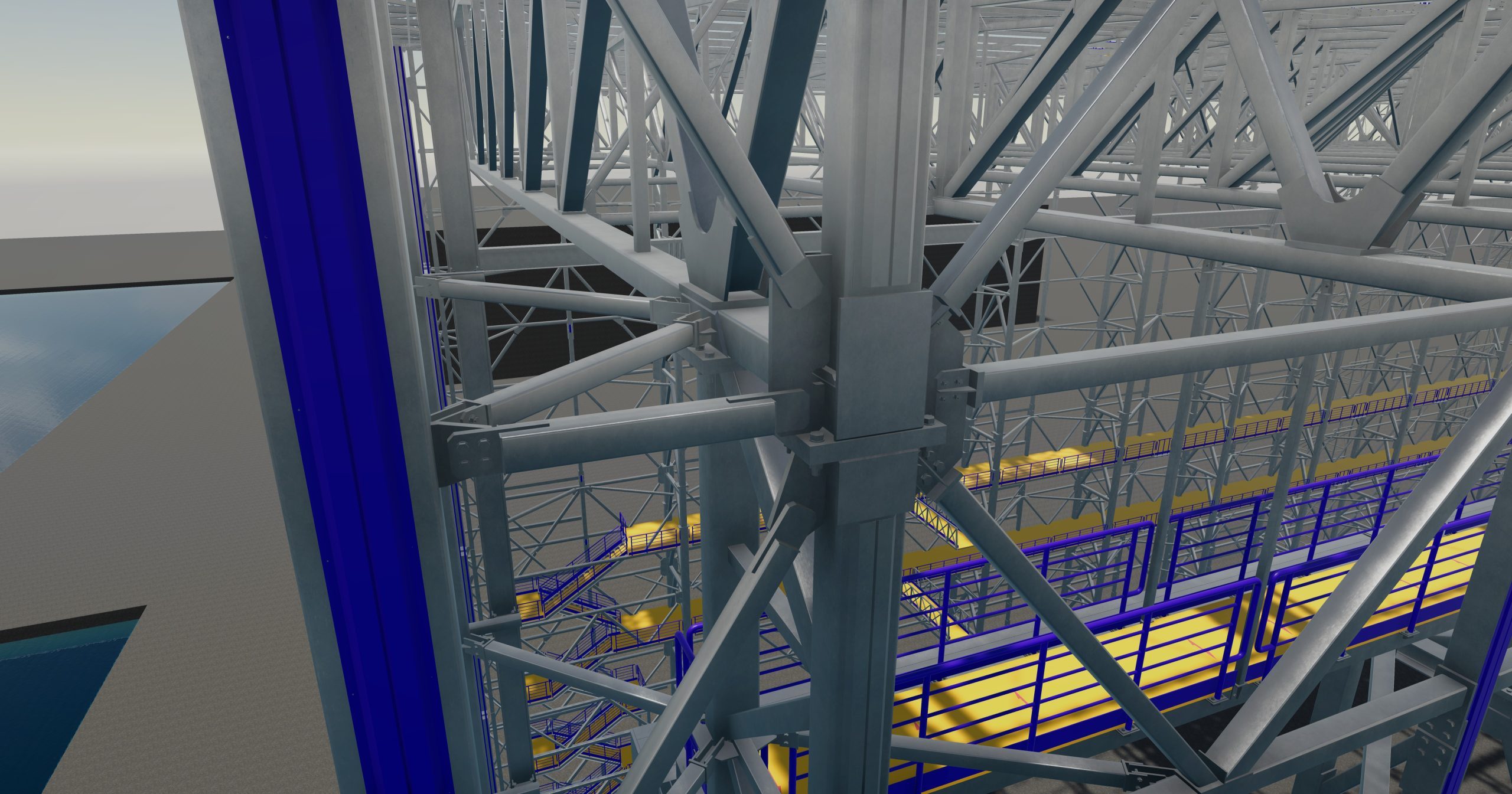
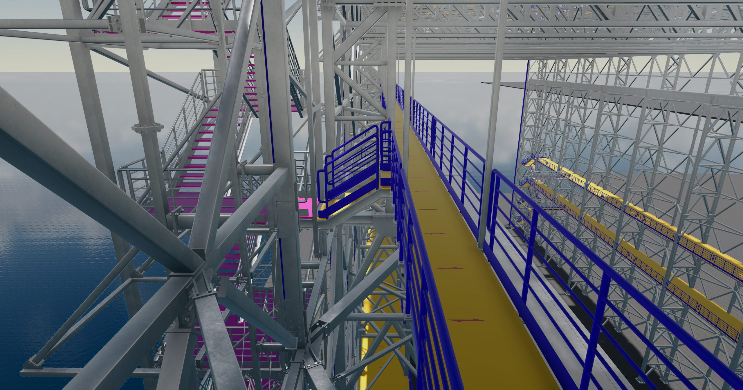
On levels +13.48 and +19.08 additional working platforms based on horizontal wall wind braces. Platforms necessary for proper communication, enabling the construction of a floating unit. Entrance to platforms via internal staircases located in the corners of the hall. In the southern part, in the immediate vicinity of the crane, an additional working platform as communication with the crane bridge and as an access element for its direct maintenance. On the roof, it is planned to make a large working platform in terms of area, connected directly to the roof structure. The number of support points of the working platform on the roof should be strictly limited in order to reduce places where vertical supporting elements penetrate the roof covering, which in places of penetrations requires significant work in order to shape an appropriate seal of the penetrations. A greater number of roof penetrations significantly increases the risk of the sheathing leaking and the occurrence of a defect that may affect the use of the building.
Steel structure placed on piles using suitably shaped reinforced concrete caps. Ground beams between the caps. Structure anchored using pre-stressed steel anchors made of max M36 (DIN 975/976) class 10.9 bars. Anchoring set consisting of steel anchors and an adapter connecting the structure to the foundation, capable of transferring a pulling force of 3.5 MN. At the level of ±0.00, the concrete floor and the ground substructure capable of transferring loads of 200 kN/m2.
It is not expected that there will be a need for expansion joints in the hull hall building. The execution of a full expansion joint of the building is burdened with significant execution risk in terms of the need to perform very precise sealing of the building, which may still be insufficient at the stage of use of the facility, due to the impact of various factors beyond the control of the Structural Designer or the General Contractor. In general, expansion joints of a hall building are planned to counteract the influence of temperature – then the structure is divided by expansion joints.
In the case of the Hull Hall under consideration, its length is approximately 154 m, and the bracing in this proposal for changes to the structural system is extremely densely spaced. Additionally, the static calculations provide for the consideration of climatic effects in the form of uniform heating and cooling of the steel structure. In view of the above, the proposal for changes to the steel structure provides for the abandonment of the expansion joints in axes 8-9 presented in the technical design.
A crane beam made of a prefabricated, prestressed, reinforced concrete beam ensuring good static work due to the dynamic impact of the cranes. The beam is capable of transferring appropriate transverse forces in both directions, a torsional moment and a bending moment in the strong and weak plane.
On the southern wall outside the hall, a steel staircase, necessary for communication between the ground level and the level of the technical platform on the roof. The staircase can be locally connected to the main structure of the hall in order to stabilize and reduce horizontal displacements. Open staircase, unenclosed.


Komentuj
Construsoft jest autoryzowanym dystrybutorem oprogramowania Tekla Structures i oferuje swoim klientom szkolenia, wsparcie techniczne i inne usługi.
Aby uzyskać więcej informacji, odwiedź naszą stronę internetową:
construsoft.plTekla is a Trimble Company © Copyright 2026 Tekla