West Tower Canopy

| Categoria | Pequenos projectos |
|---|---|
| Ano | 2023 |
| País | Poland |
| Organização | Arucon Sp. z o.o. |
| Autor | Arucon |
| Local de construção | Londyn |
| Tags |
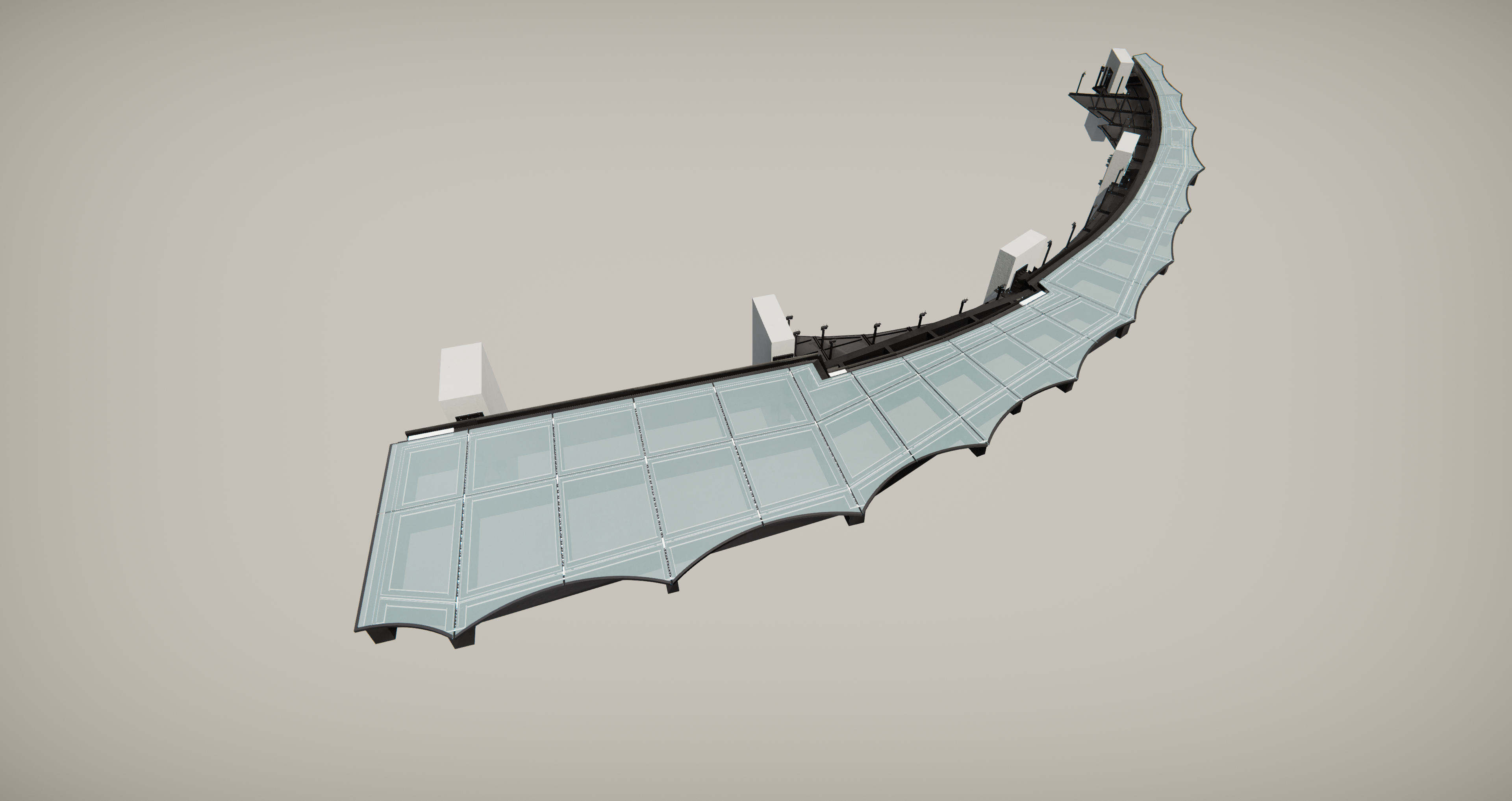
Projekt zadaszenie zewnętrznego na zachodniej wieży kompleksu 3 wieżowców „Consort Place” w Londynie.
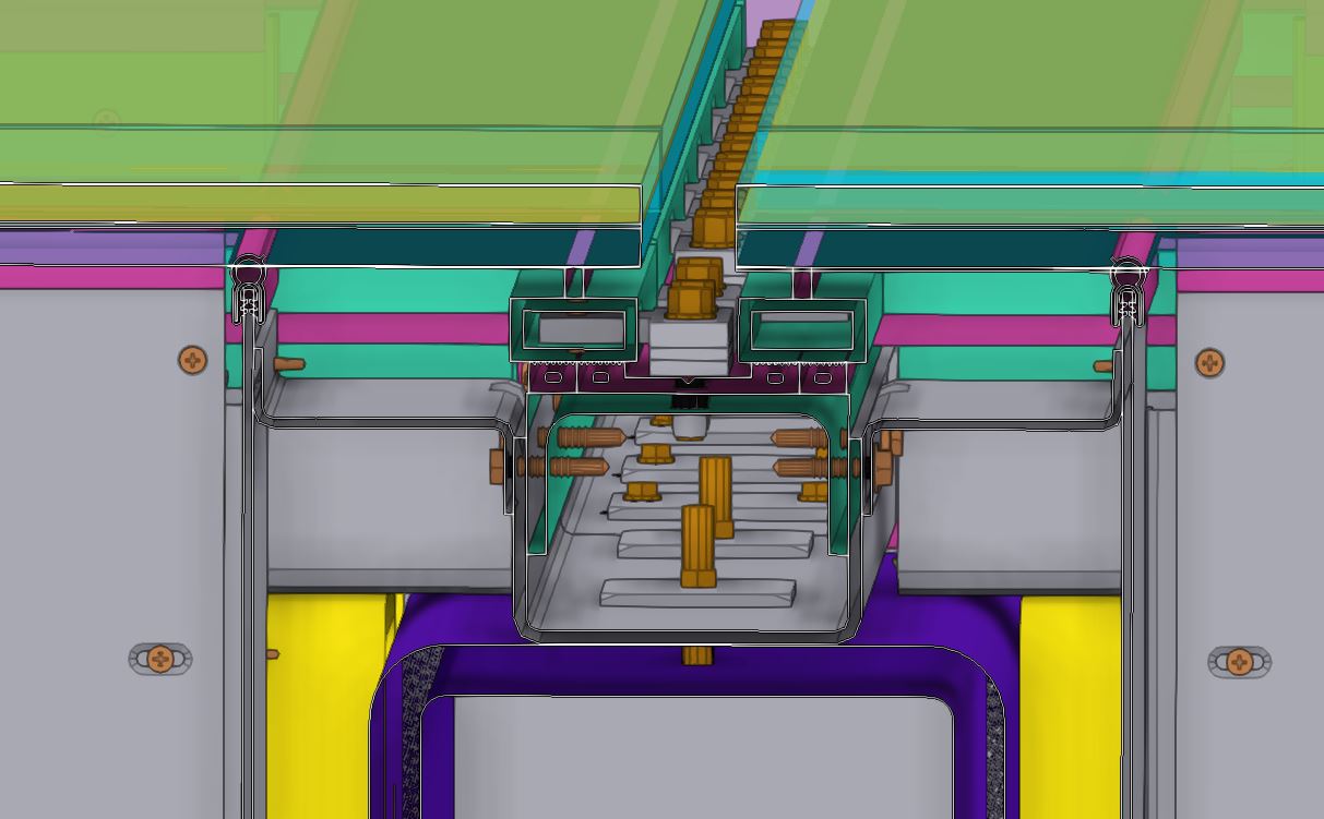
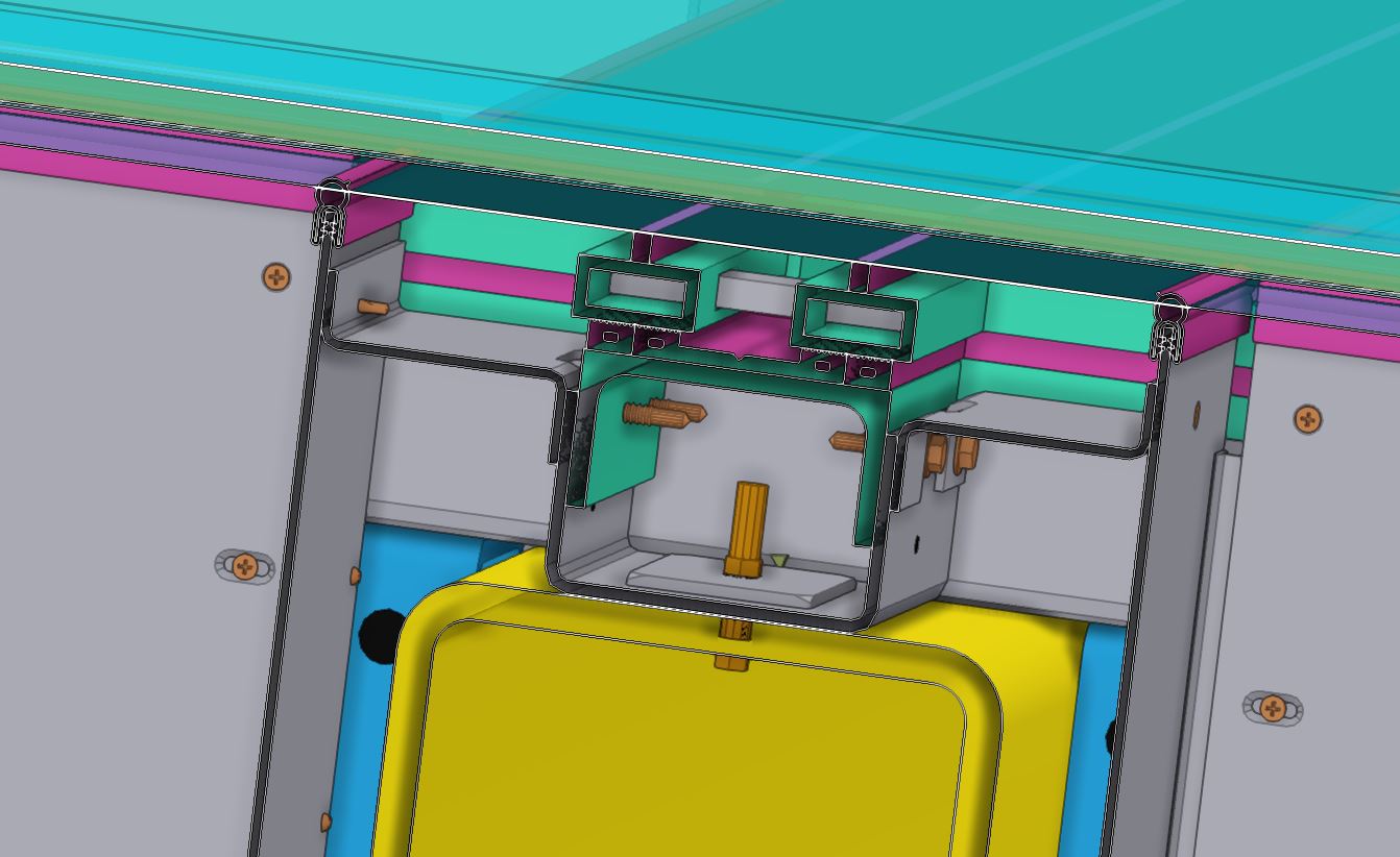
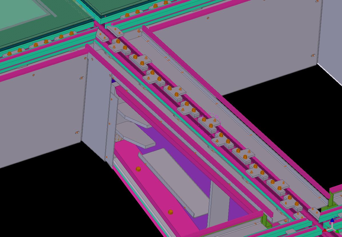
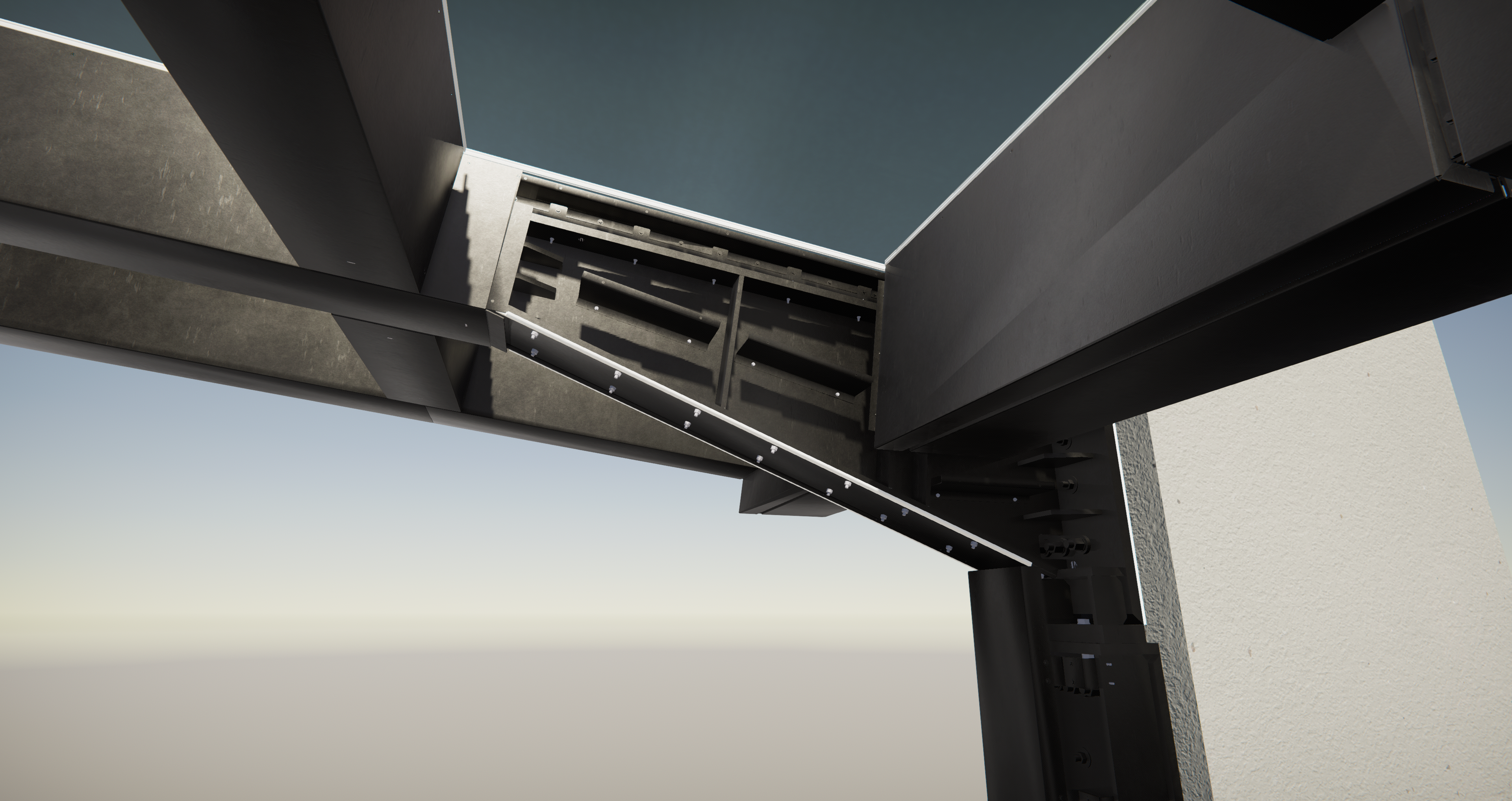
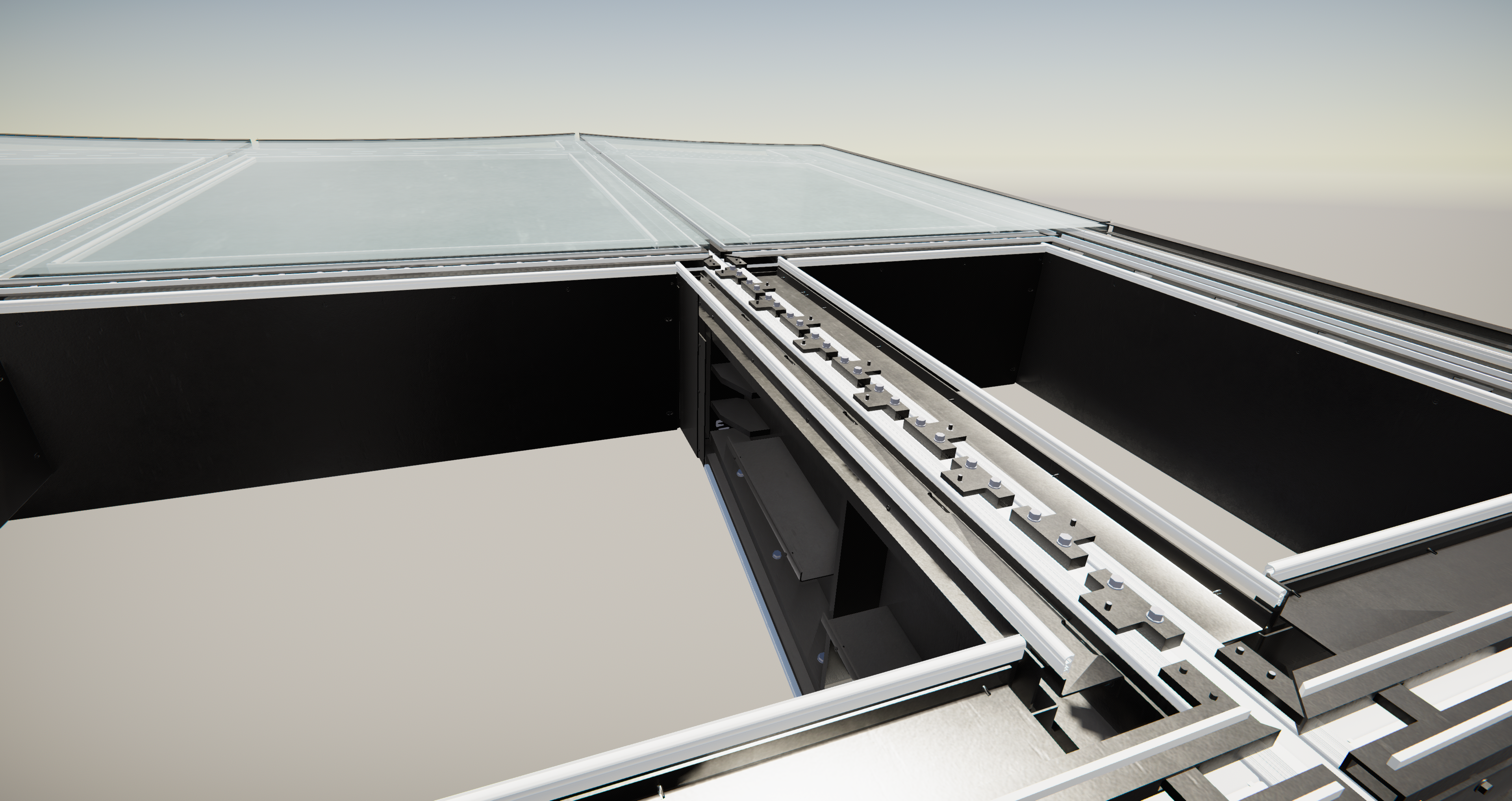
W ramach projektu wykonany został model konstrukcji stalowej zadaszenia wraz fasadą, w tym obróbkami aluminiowymi, rynną, sufitami, szkleniem, a także uszczelkami. Z uwagi na dużą dokładność wykonania, na modelu zostały naniesione nawet żłobienia pod śruby φ4.8mm z łbem wpuszczanym, tak aby po zmontowaniu konstrukcji żadna ze śrub nie wystawała poza lico blach.
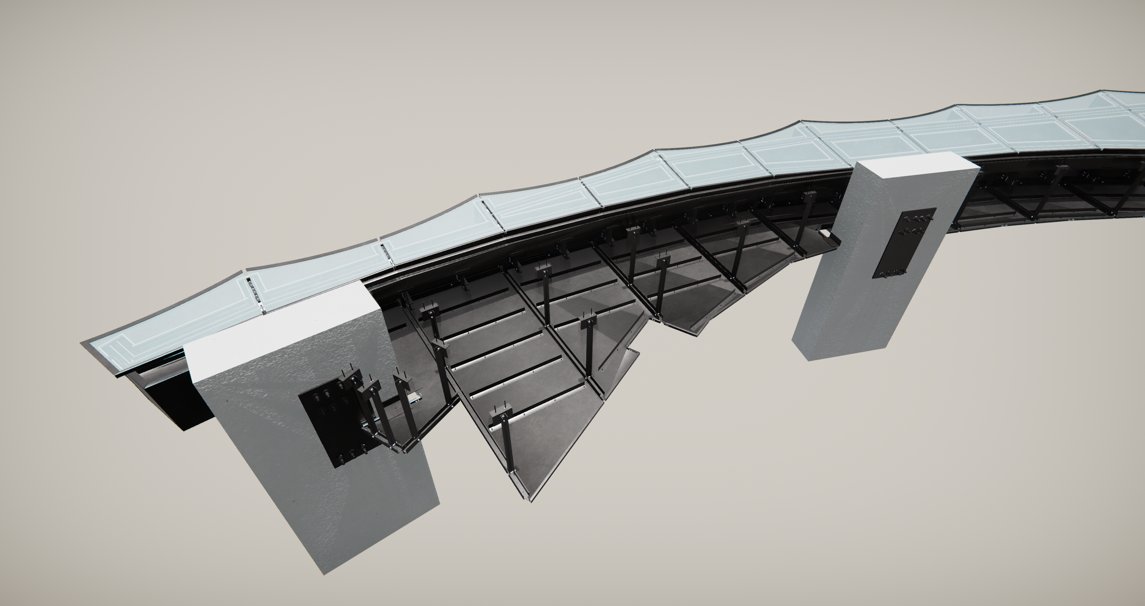
Innym aspektem projektu była konieczność przesłonięcia konstrukcji znajdującej się pod szkłem, tak aby osoba patrząca z góry jej nie mogła dostrzec. Zapewniono to poprzez malowanie spodniej powierzchni szkła smarem, który także został zamodelowany w Tekli.
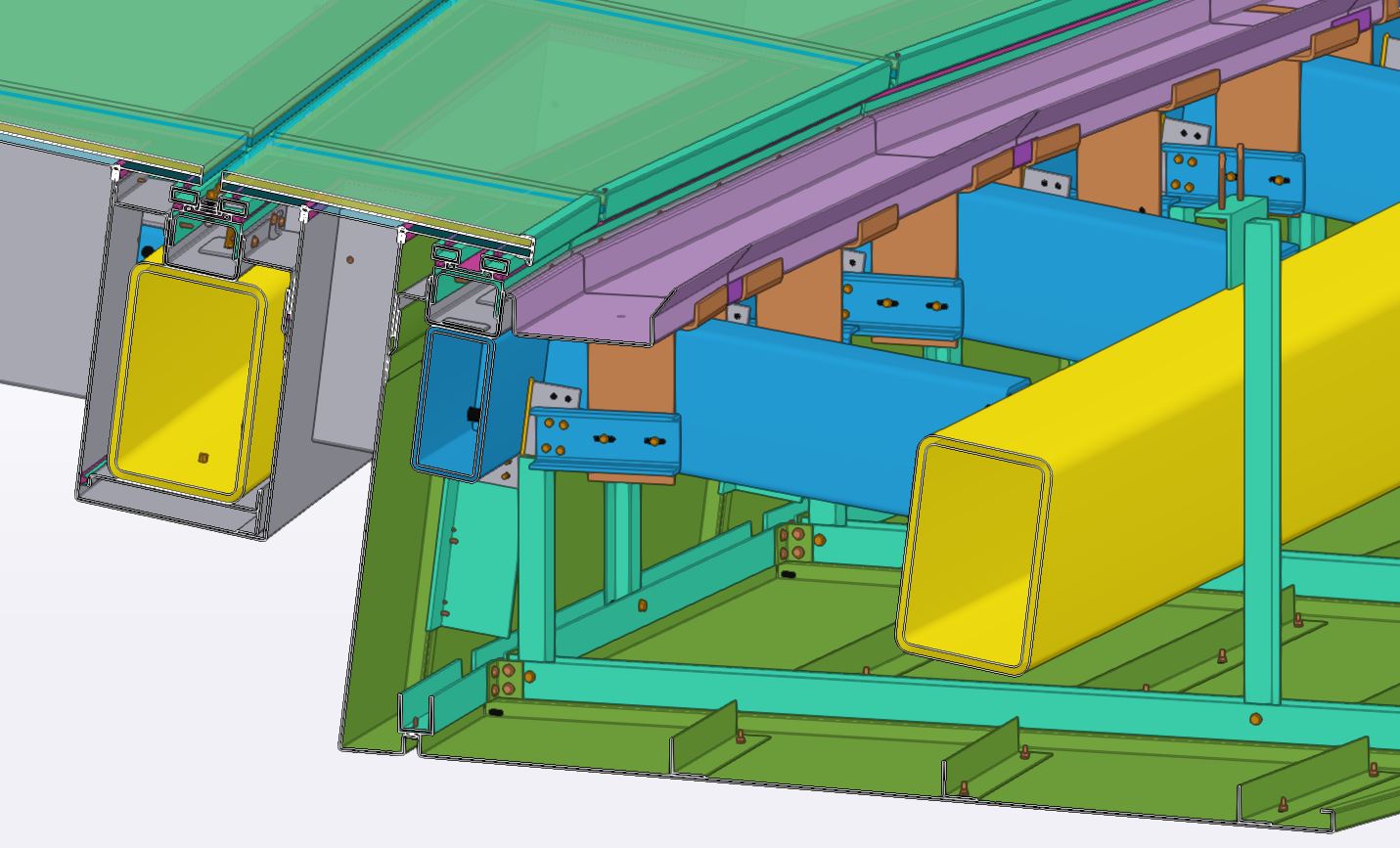
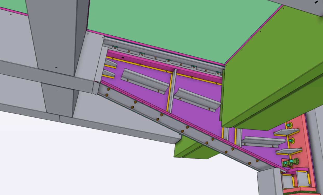
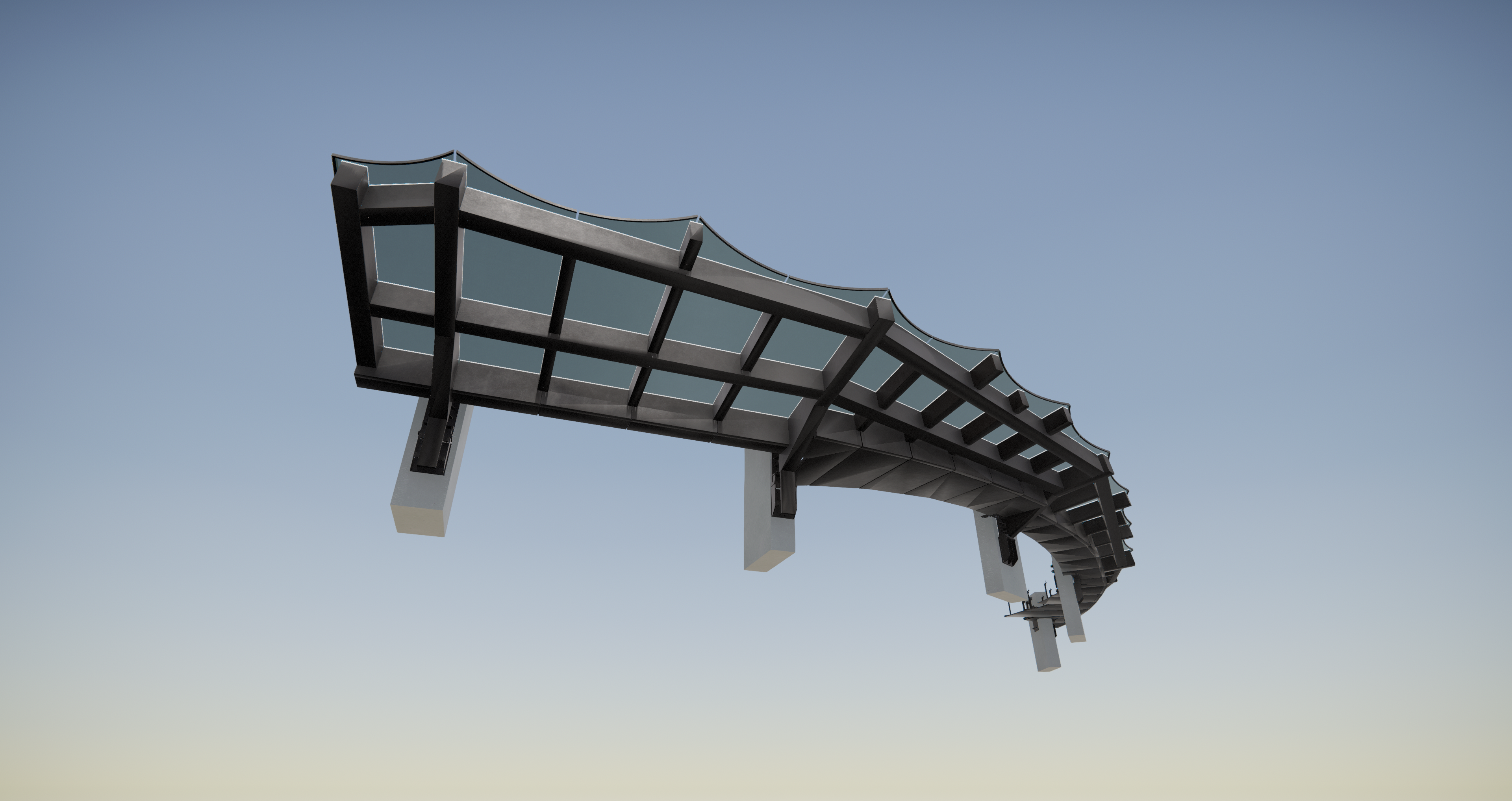
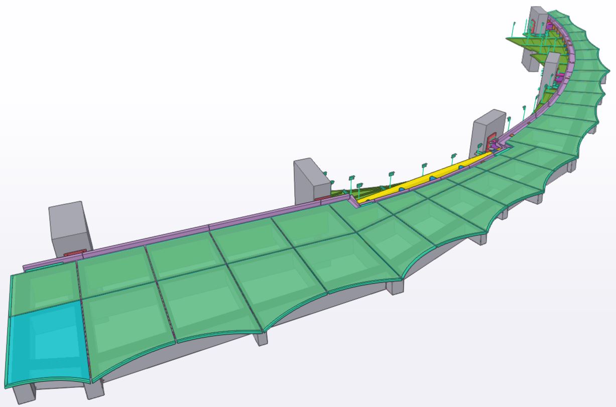
Jednym z większych wyzwań projektu, oprócz wysokiego poziomu detalowania widocznego na załączonych widokach, była konieczność koordynacji naszej części fasady modelowanej w 3D z fasadą budynku, która jednocześnie była projektowana w 2D.
Dla całości dokumentacji, tj.: dla konstrukcji stalowej, aluminiowej, szkła oraz uszczelek sporządzono rysunki warsztatowe oraz montażowe. Łączna liczba elementów w modelu Tekli wyniosła ponad 24 000.
The design of the external roof on the west tower of the complex of 3 skyscrapers “Consort Place” in London.
As part of the project, a model of the steel structure of the roof with the facade was made, including aluminum flashings, gutter, ceilings, glazing and gaskets. Due to the high precision of workmanship, even grooves for φ4.8mm countersunk head screws were marked on the model, so that after assembling the structure none of the screws protrudes beyond the face of the sheets.
Another aspect of the design was the need to cover the structure under the glass so that a person looking from above could not see it. This was ensured by painting the underside of the glass with smear, which was also modeled in Tekla.
One of the biggest challenges of the project, in addition to the high level of detail visible in the attached views, was the need to coordinate our part of the facade modeled in 3D with the facade of the building, which was simultaneously being designed in 2D.
Workshop and assembly drawings were prepared for the entire documentation, i.e. for the steel and aluminum structure, glass and gaskets. The total number of elements in the Tekla model was over 24,000.

Deixe o seu comentário
A Construsoft é revendedor autorizado de Tekla Structures e disponibiliza formação, suporte técnico e outros serviços aos seus clientes.
Para mais informações, visite nosso site:
construsoft.ptTekla is a Trimble Company © Copyright 2026 Tekla
Impressive