 A kategória győztese országonként
Multifunkční fotbalový stadion Hradec Králové
| Kategorie | Kleine Projekte |
|---|---|
| Jahr | 2024 |
| Land | Czech Republic |
| Organisation | SKÁLA & VÍT, s.r.o. |
| Projektpartner | Tomáš Vymetálek Architects s.r.o., ARCHAaPLAN s. r. o., Geodézie Východní Čechy spol. s r. o., sdružení Strabag, Geosan Grup, D&D Elektromont |
| Verfasser | Ing. Vladímír Ferkl, Ing. Ivan Šemík |
| Mitverfasser | Kolektiv firmy SKÁLA & VÍT, s.r.o. |
| Auftraggeber | Statutární město Hradec Králové |
| Ort des Bauwerkes | Hradec Králové |
| Tags | ConcreteTekla StructuresTrimble ConnectSteel |
MULTIFUNKČNÍ FOTBALOVÝ STADION HRADEC KRÁLOVÉ
• Investor: Statutární město Hradec Králové
• Metoda výstavby: Design & Build
• Architekt: Tomáš Vymetálek Architects
• Hlavní projektant: ARCHaPLAN
• Konstrukce: SKÁLA & VÍT, s.r.o.
• Dodavatel stavby: sdružení Strabag, Geosan Grup, D&D Elektromont
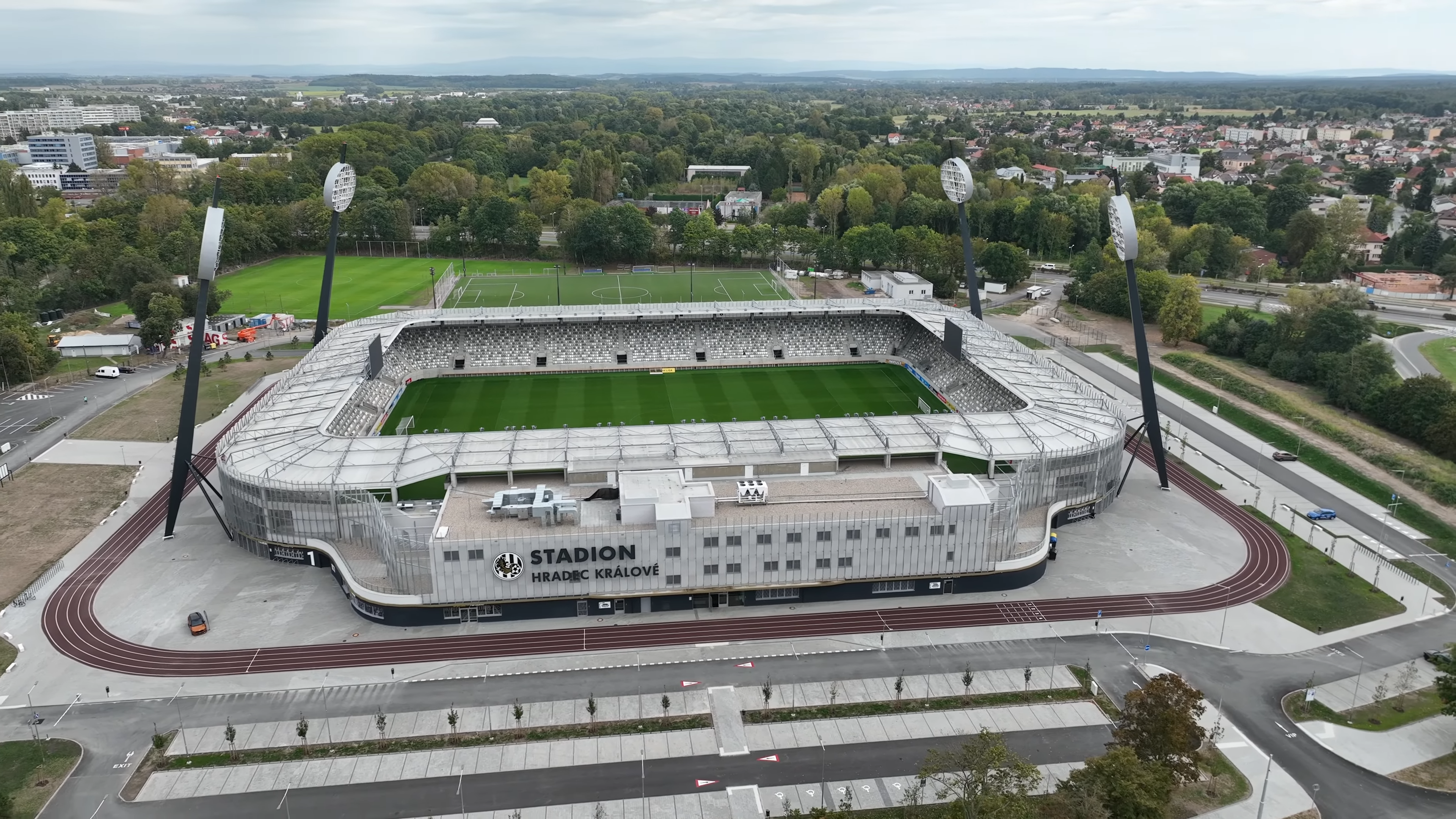
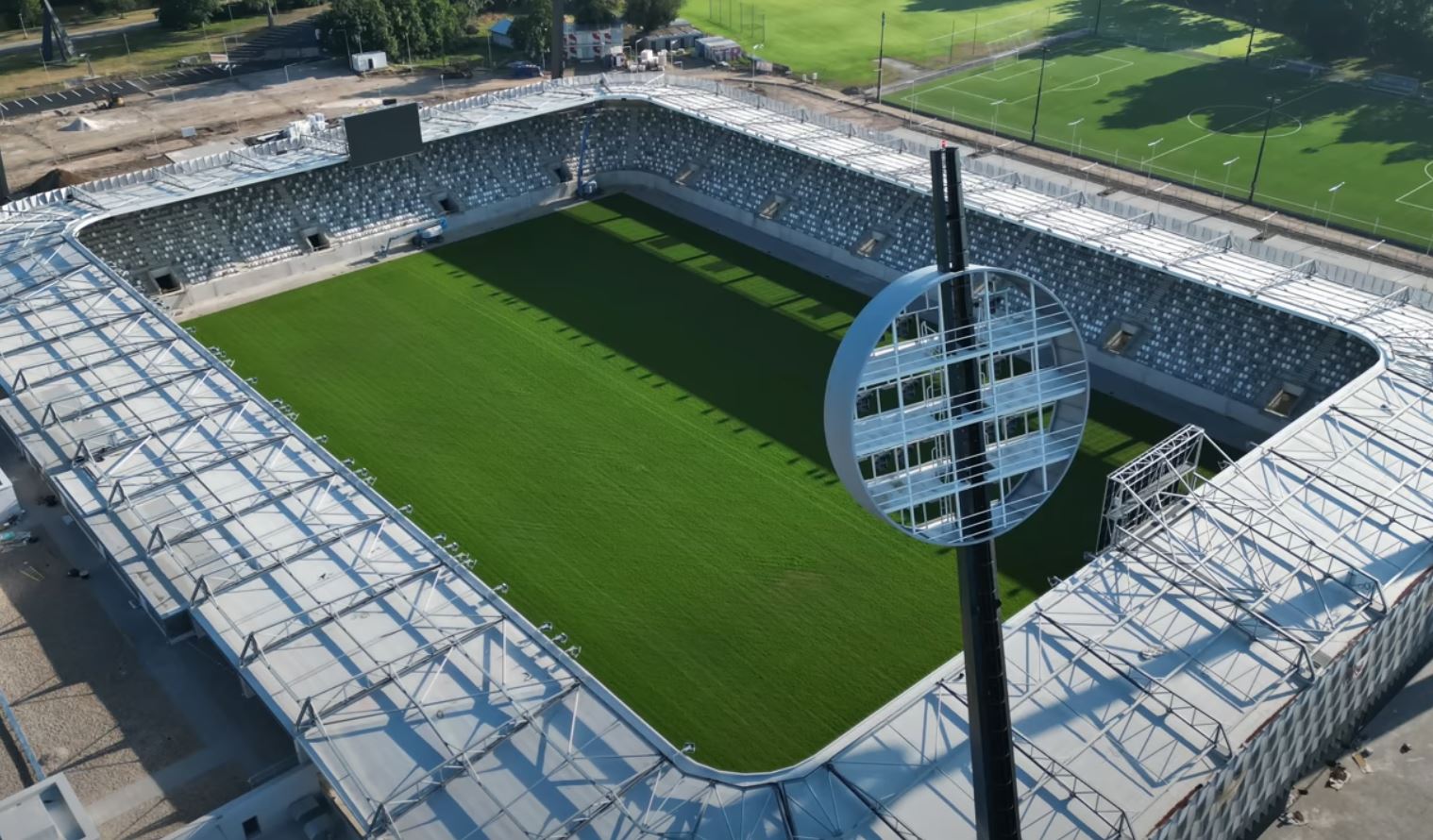
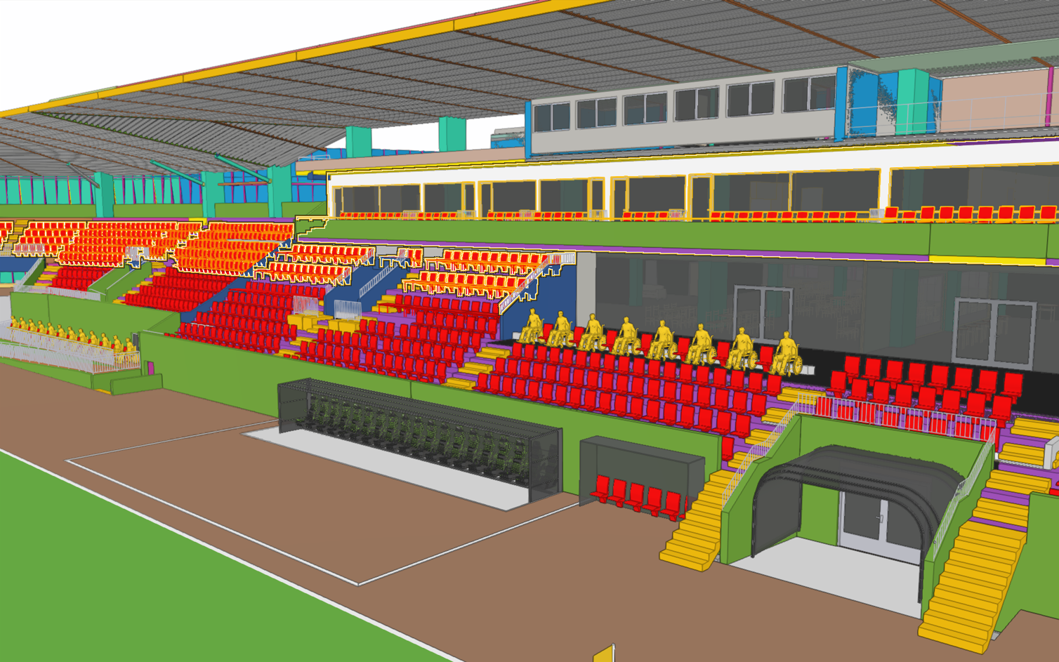
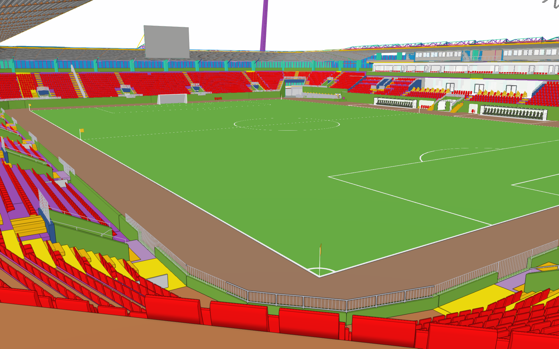
• Kapacita: 9300 diváků, všechna místa krytá, určená k sezení
• Kapacita VIP prostor: 500 míst
• Kapacita skyboxů: 210 míst
• Zahájení stavebních prací: 2. srpna 2021
• Kolaudace: 2. srpna 2023
• První zápas: 5. srpna 2023
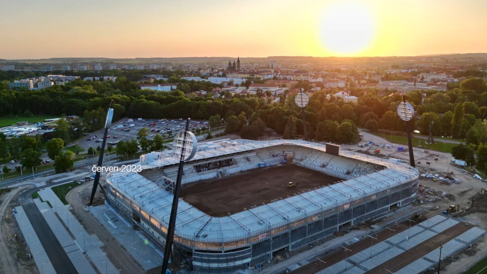
• Slavnostní otevření: 3. září 2023
• Zajímavá videa o stadionu:
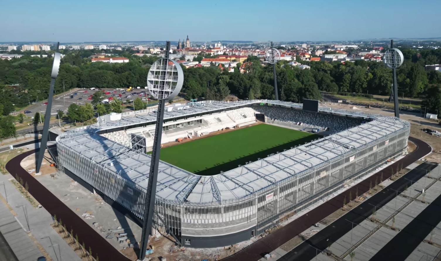
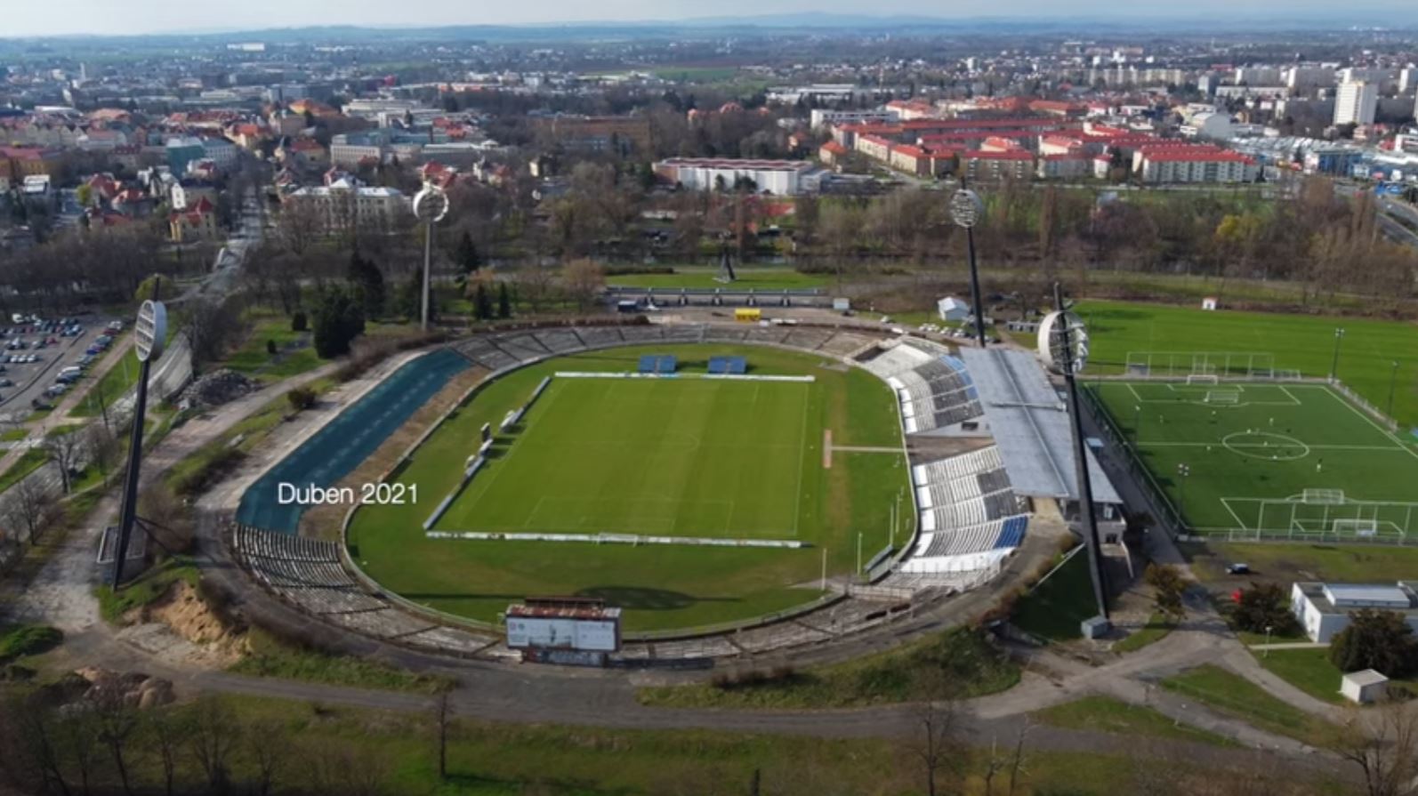
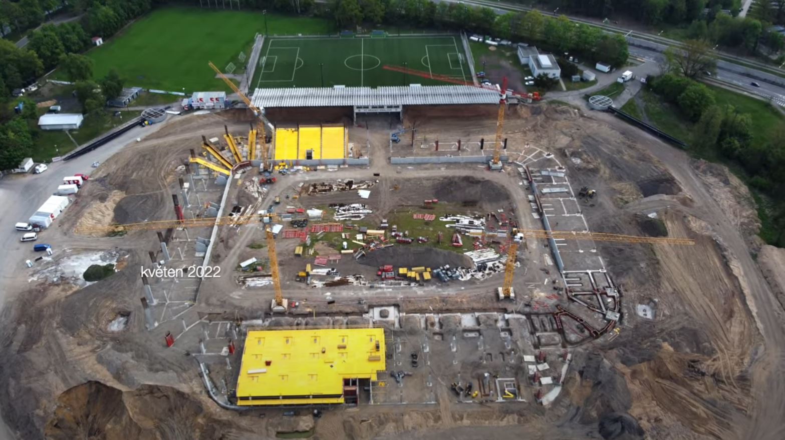
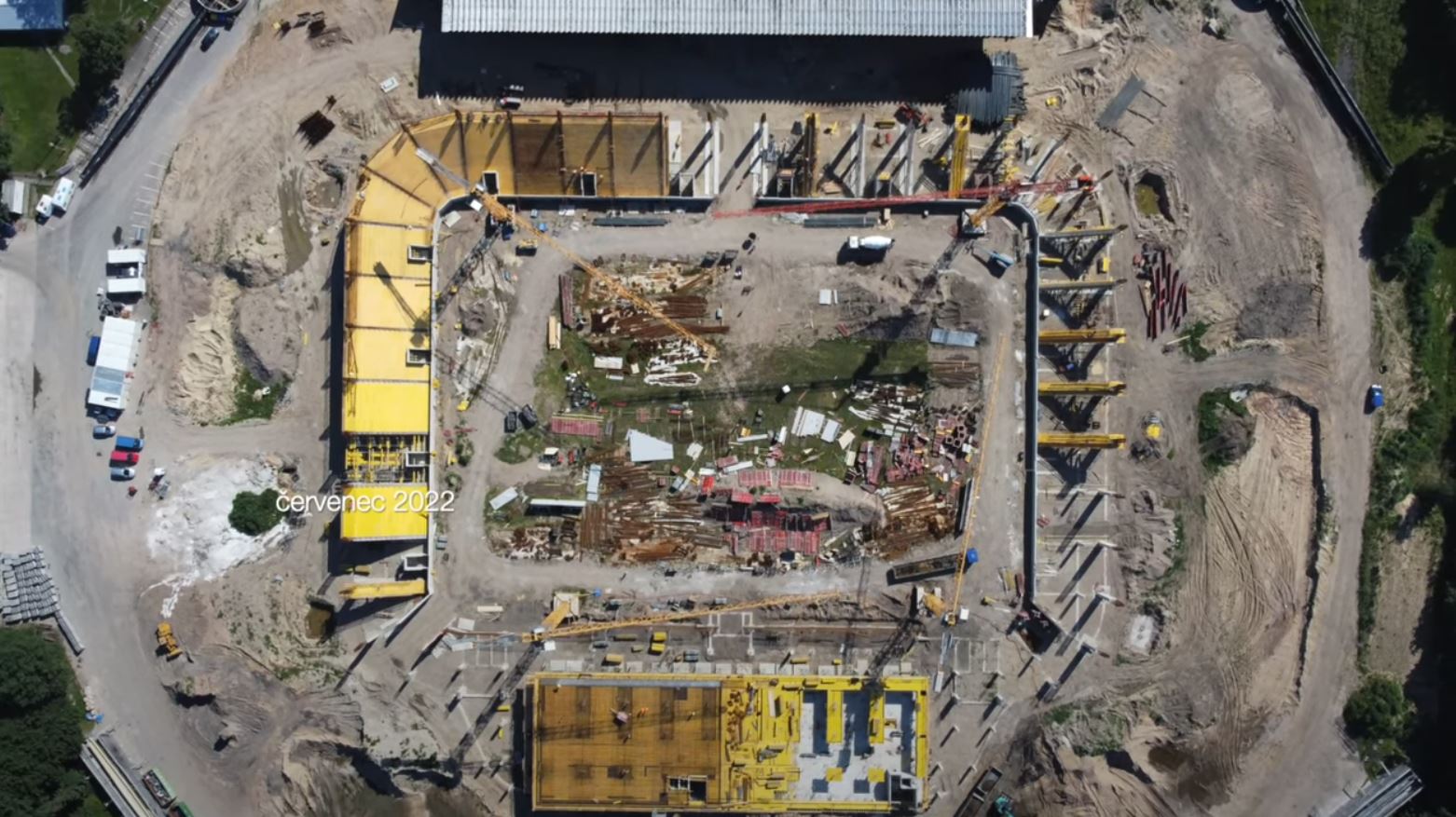
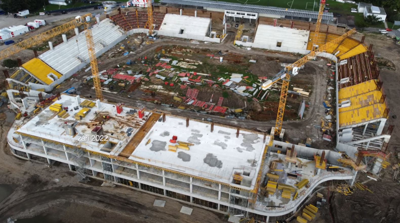
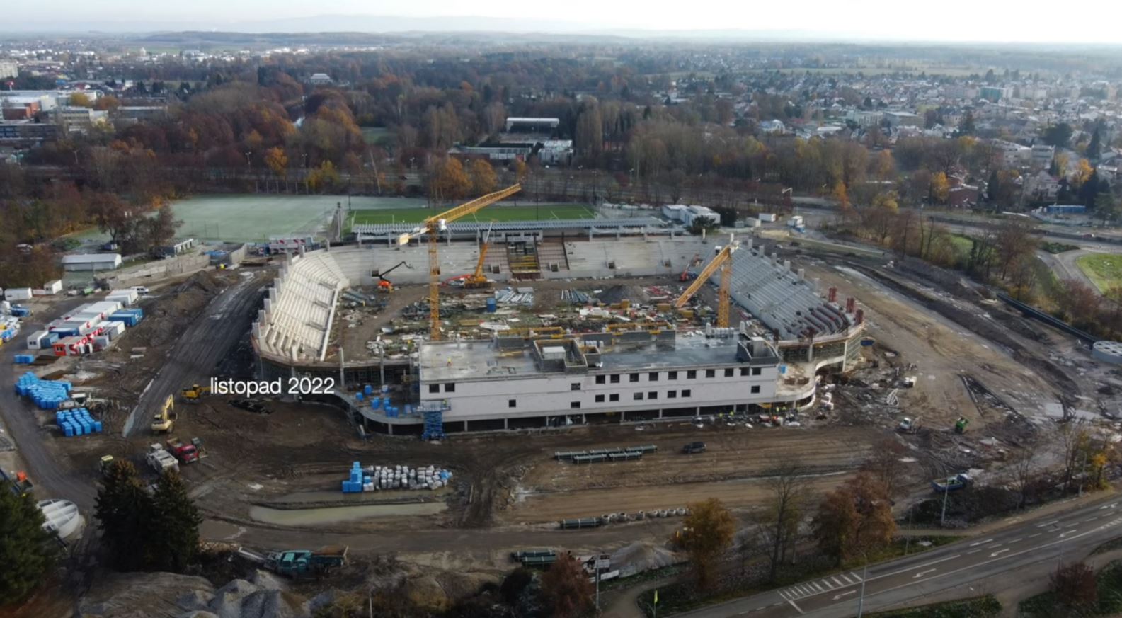
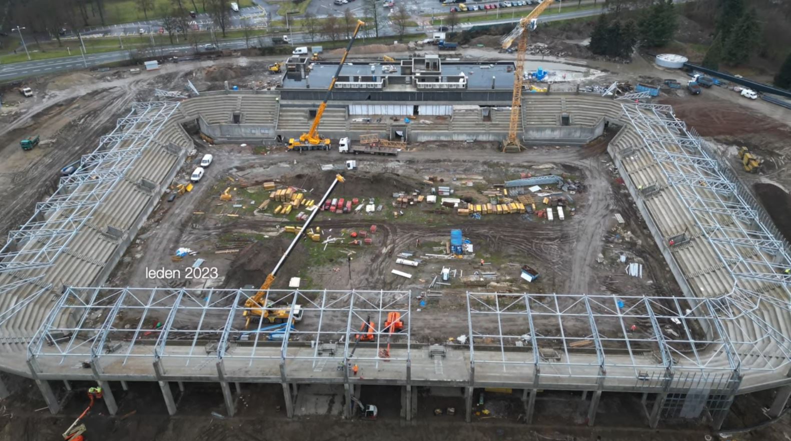
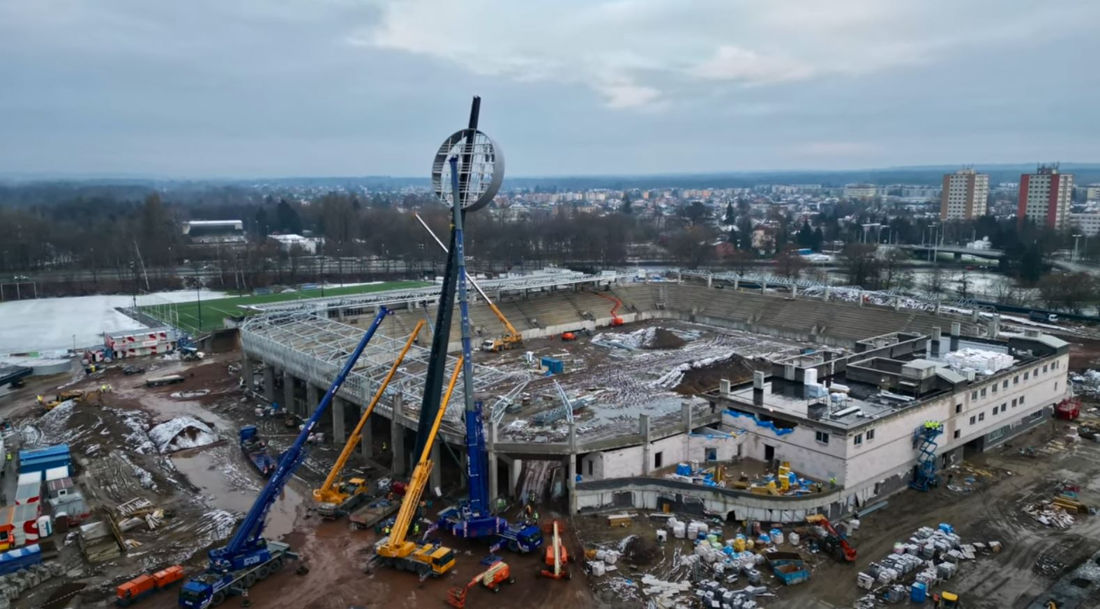
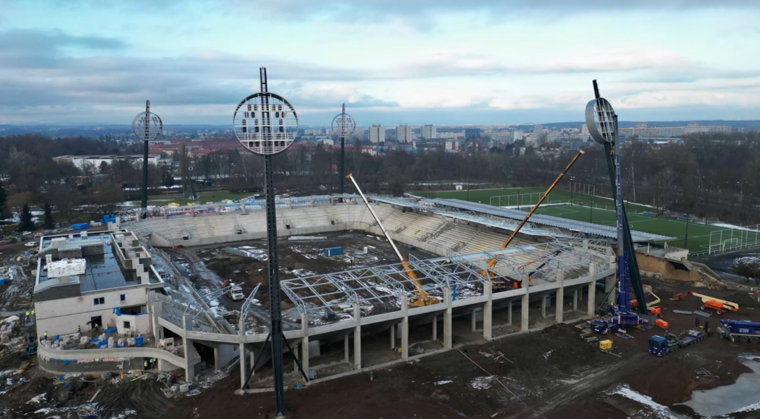
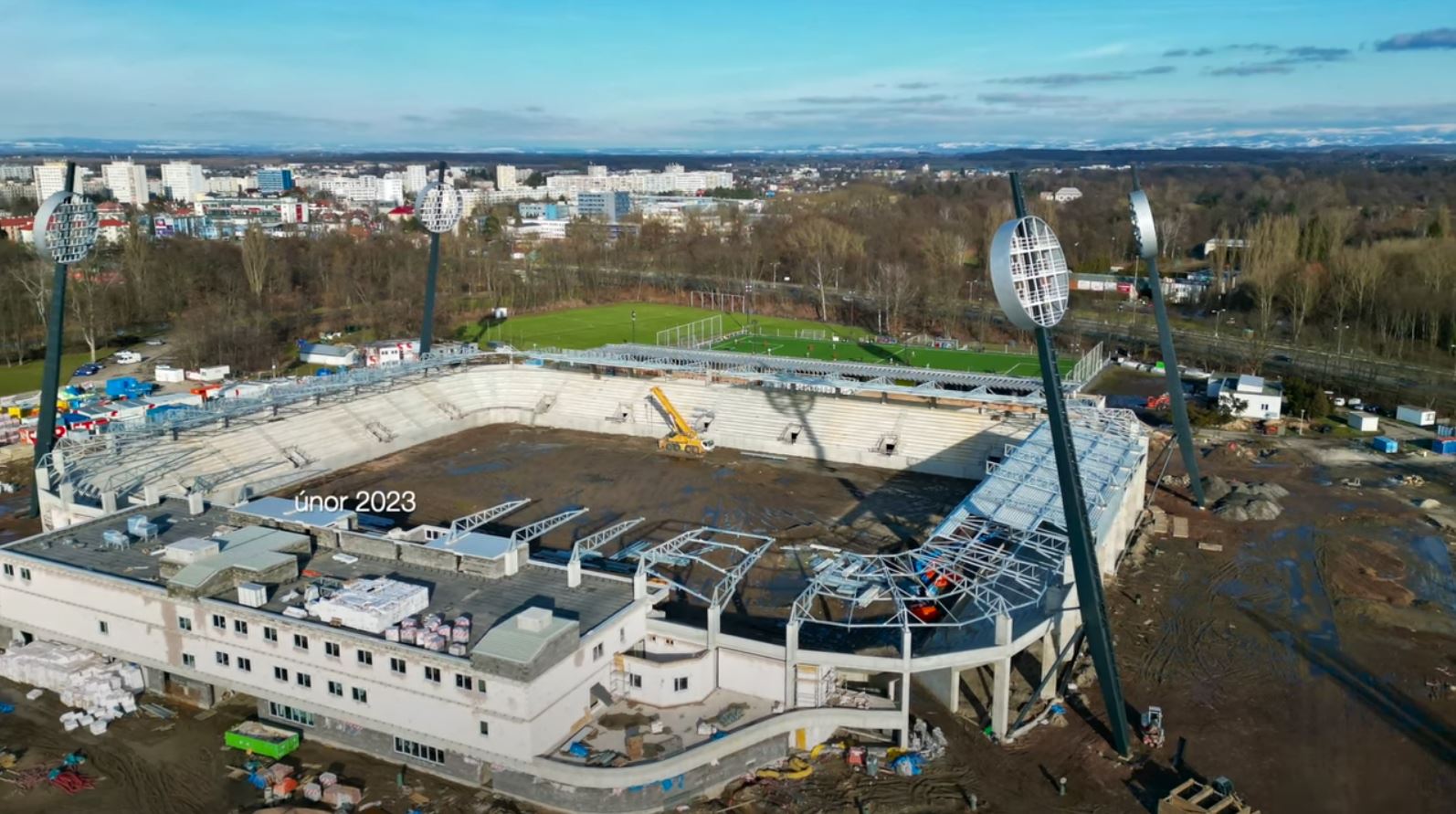
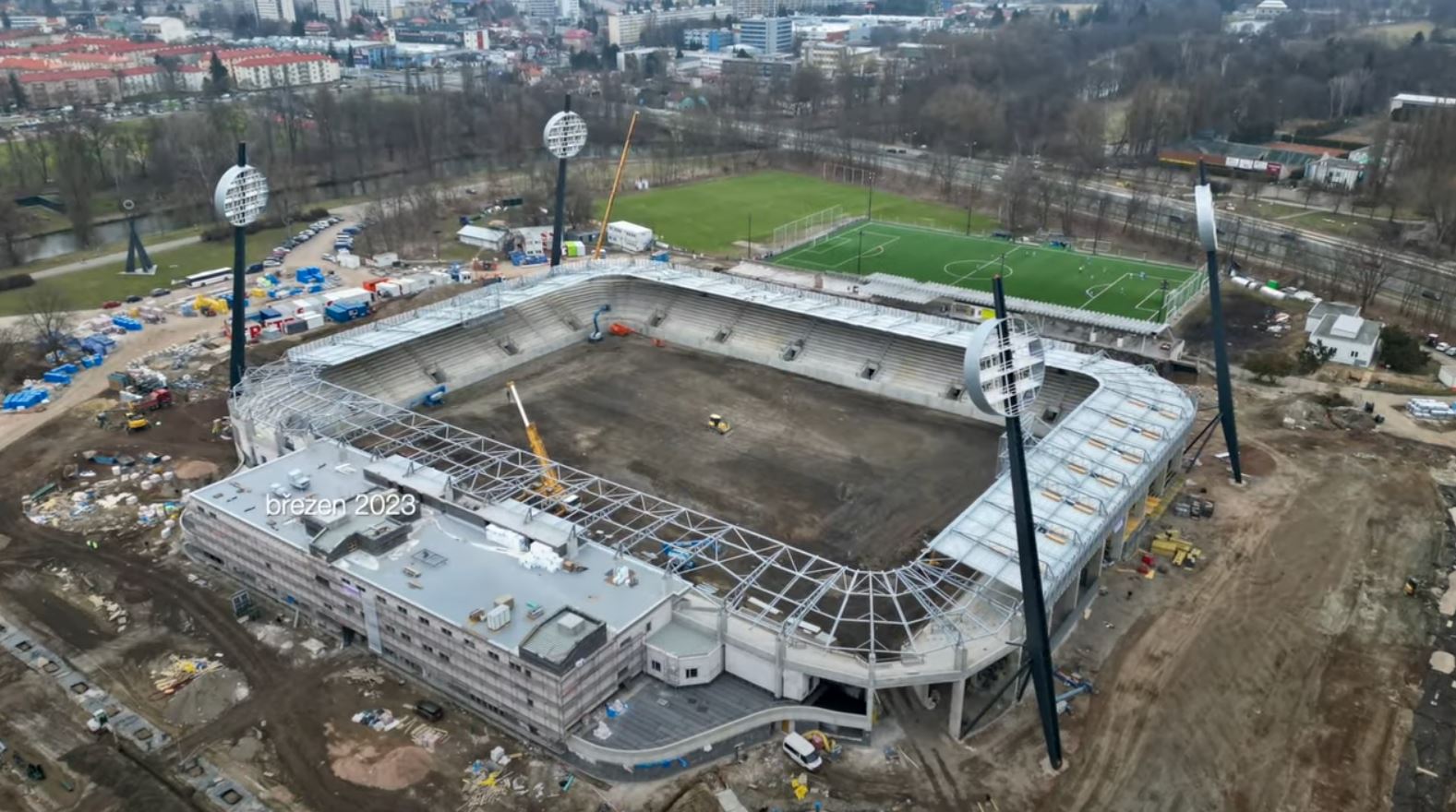
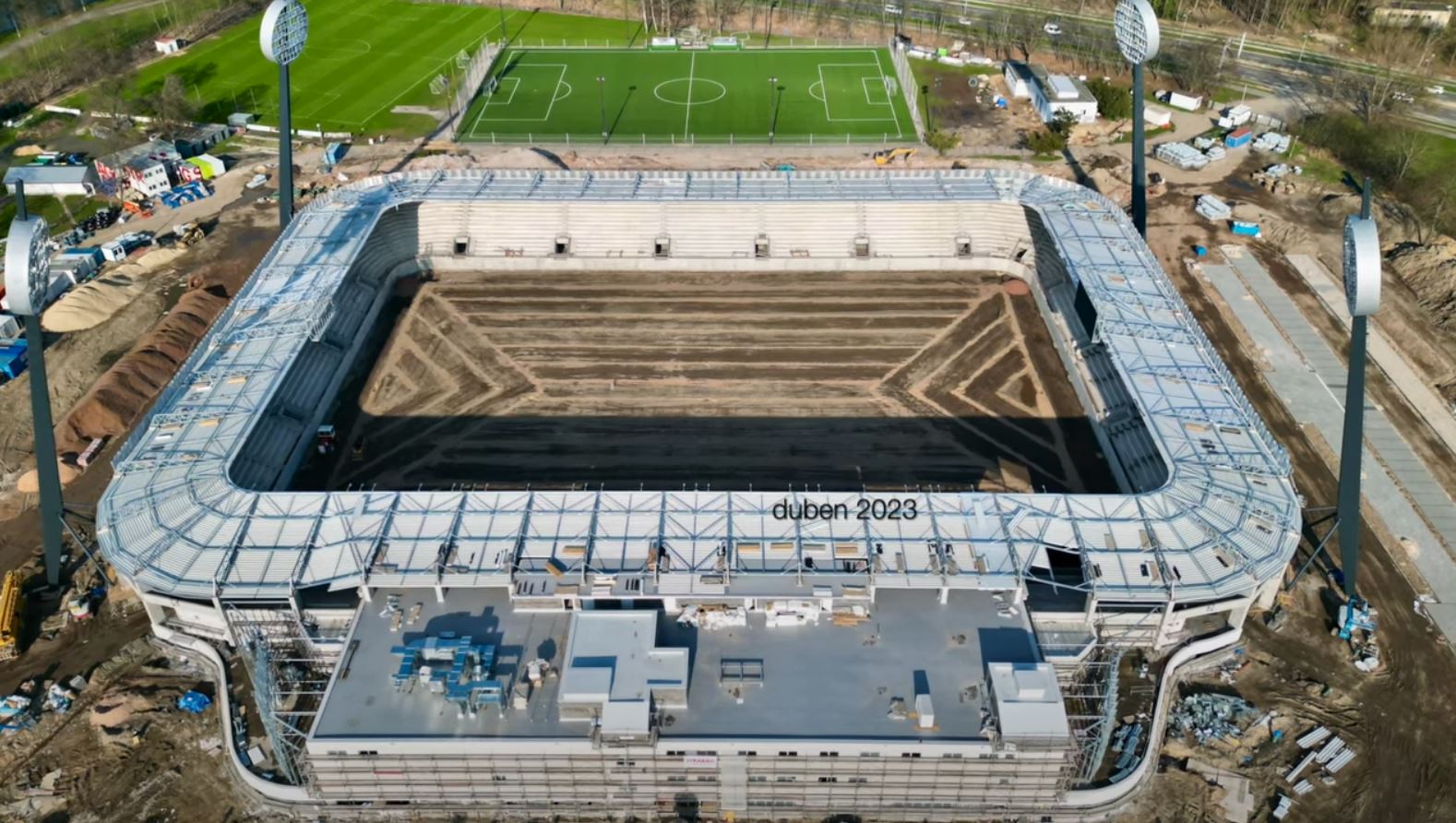
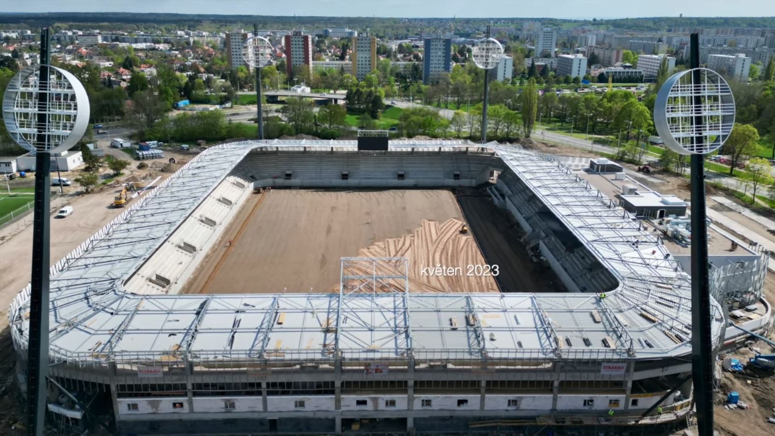
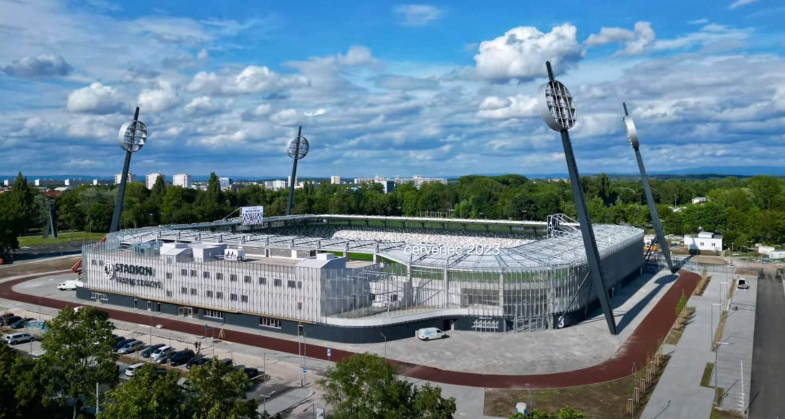
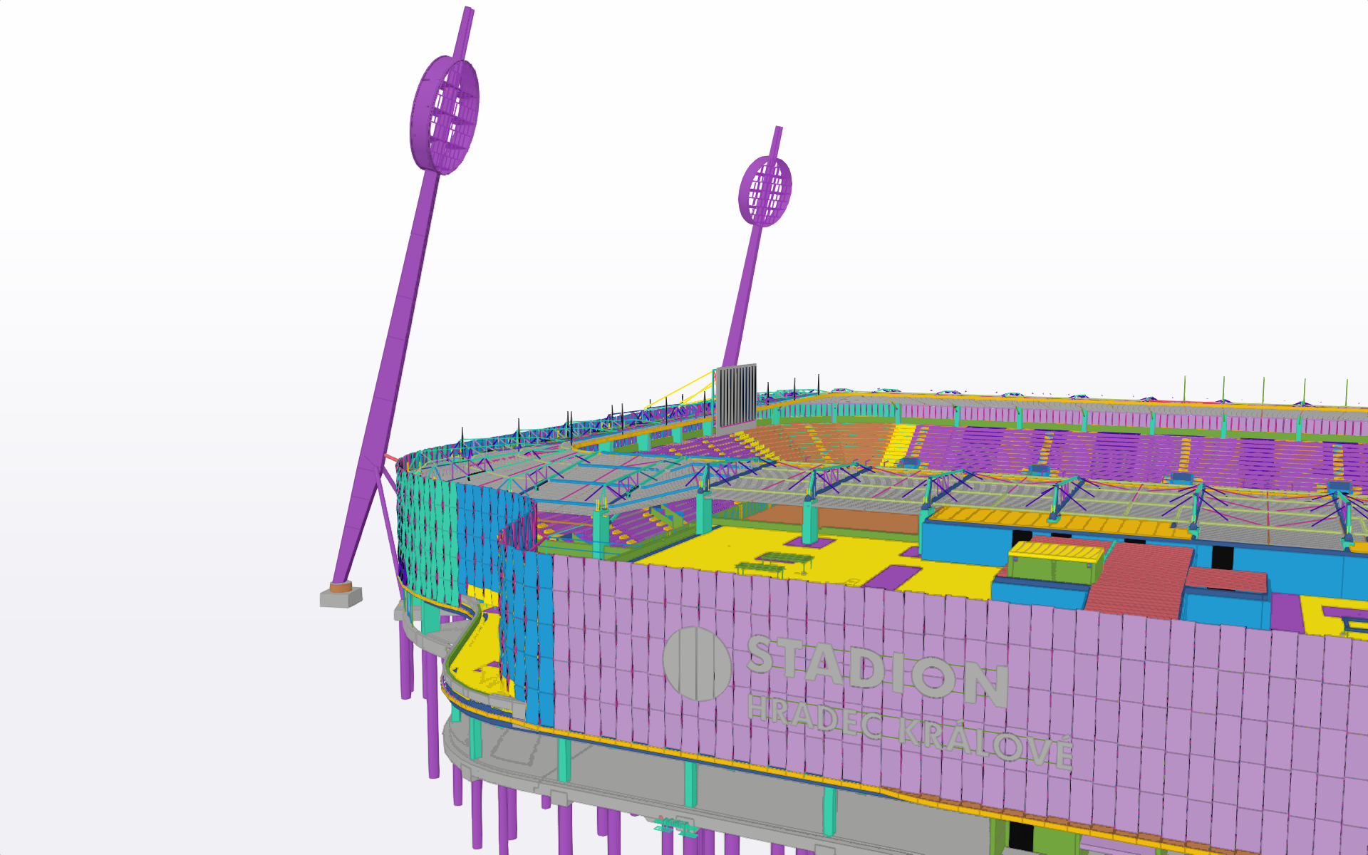
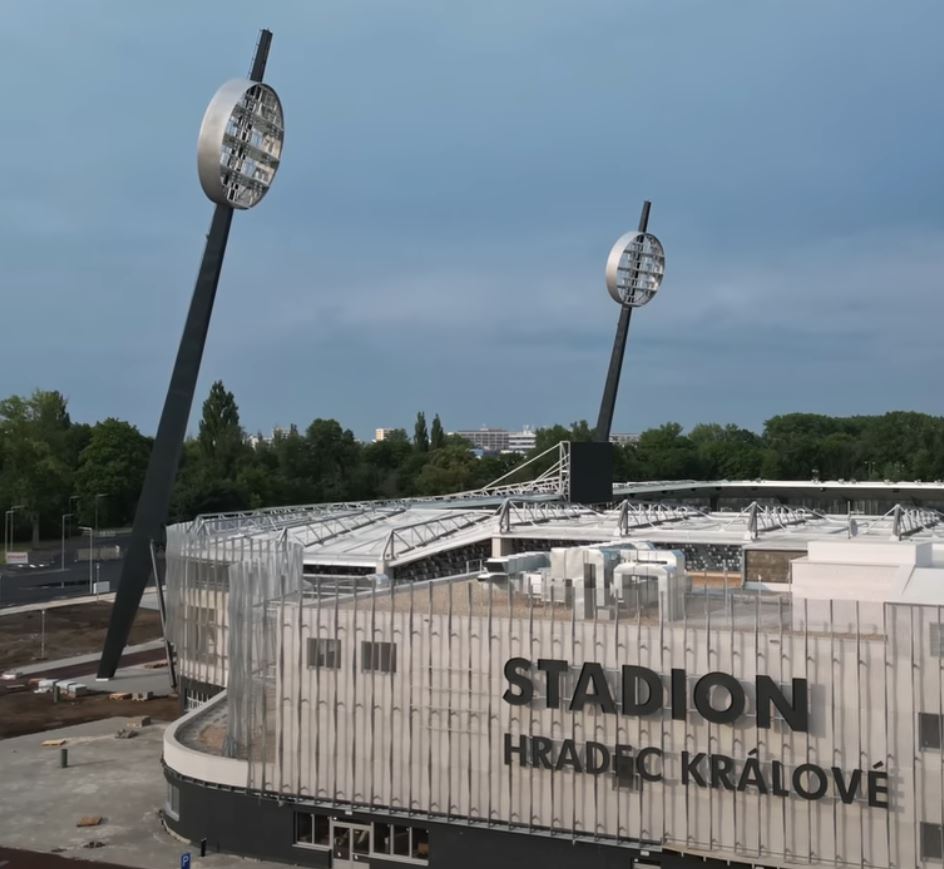
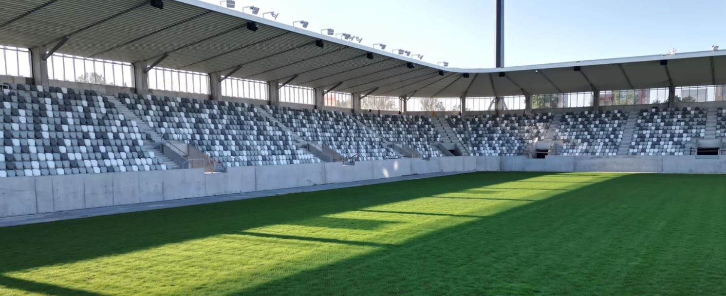
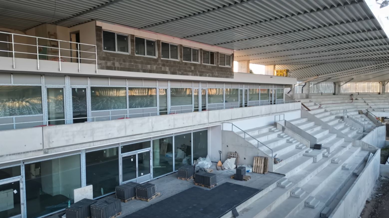
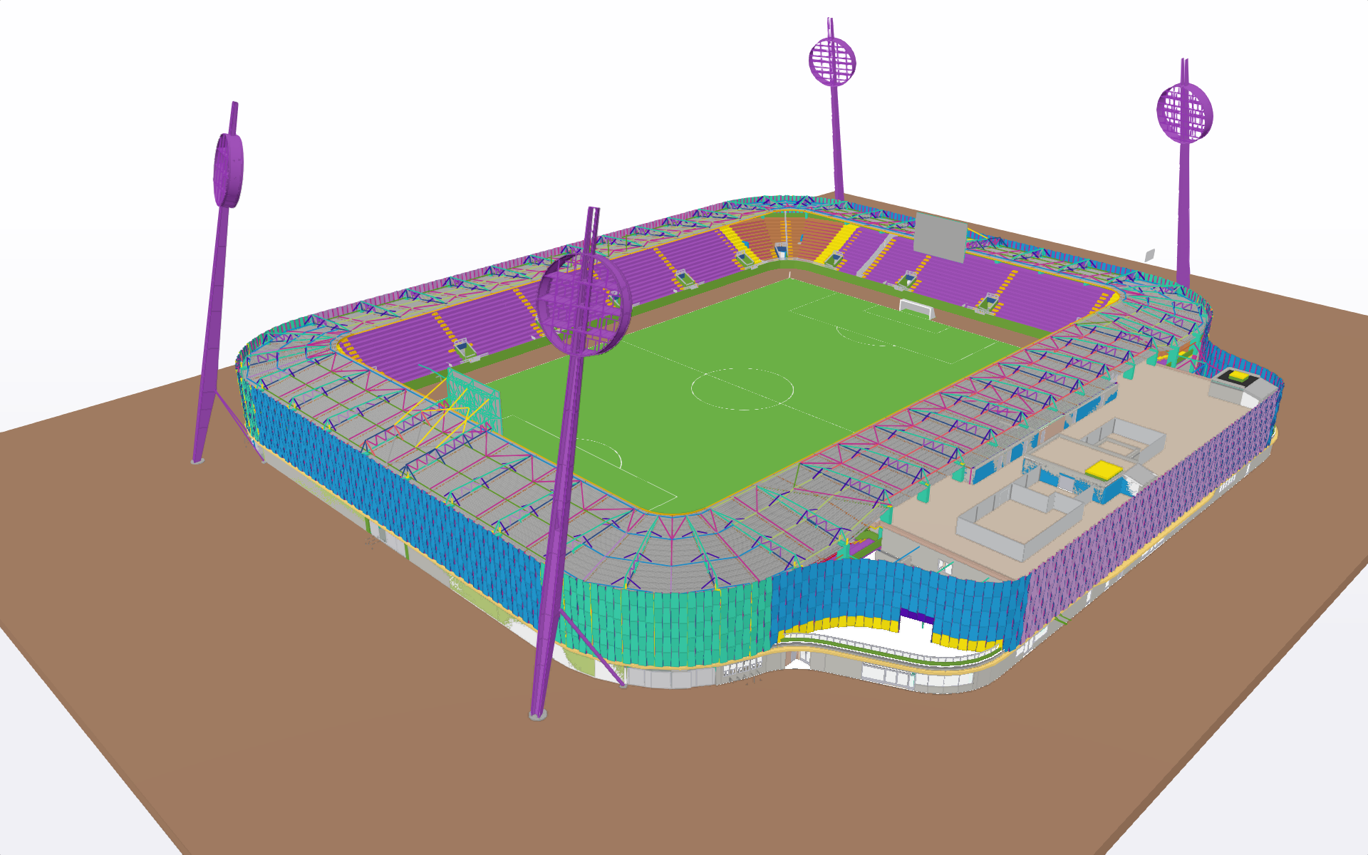
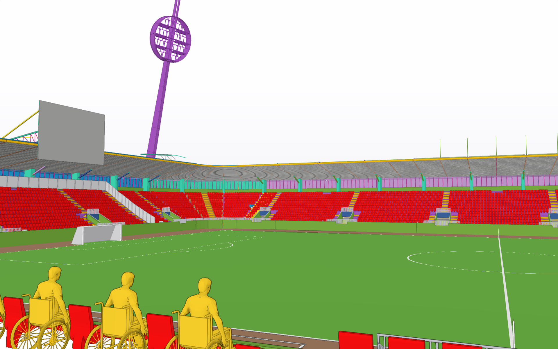
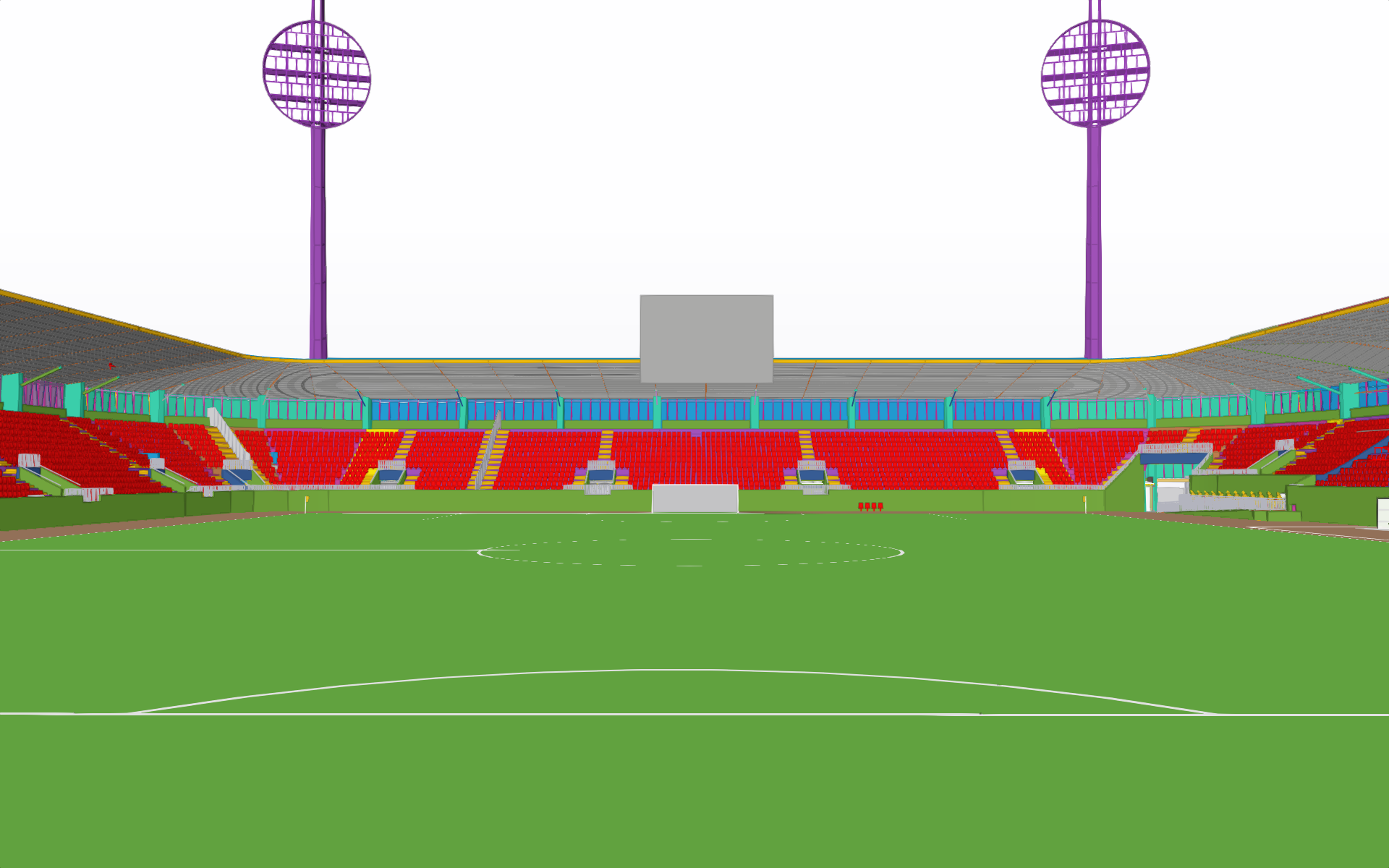
Malšovická aréna vznikla v letech 2022 a 2023 na místě dřívějšího Všesportovního stadionu v Hradci Králové. Ten byl postaven již v roce 1970, o patnáct let později k němu byla vztyčena i „slavná lízátka“, která díky nadšení realizačního týmu, zůstala zachována i pro novou arénu.
Historický stadion již několik let neodpovídal prvoligovým standardům, proto ho bylo nutno nahradit moderním svatostánkem. Po návratu Hradce Králové do nejvyšší soutěže museli Votroci pro sezóny 2021/22 a 2022/23 do mladoboleslavského azylu Lokotrans arény.
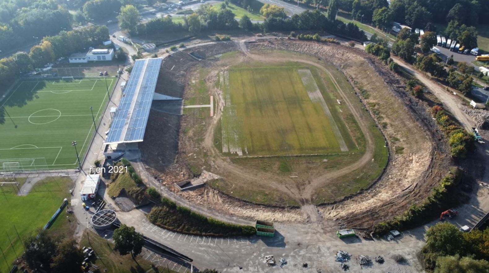
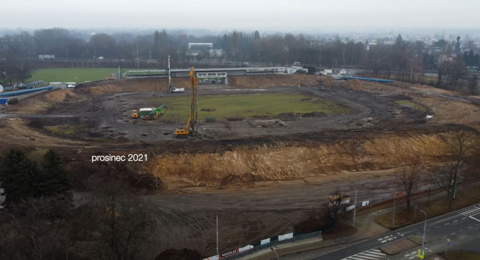
Výstavba moderního multifunkčního stadionu v Malšovicích byla schválena v březnu roku 2021 a stavby se ujalo vítězné sdružení firem Strabag, Geosan Group a D&D Elektromont.
PROJEKT:
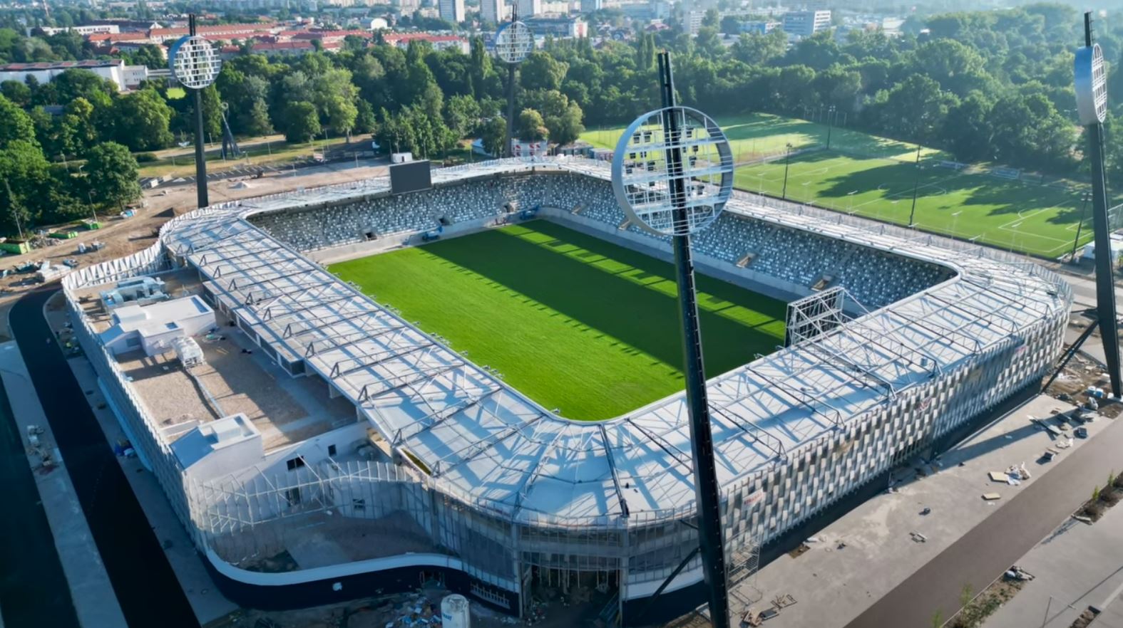
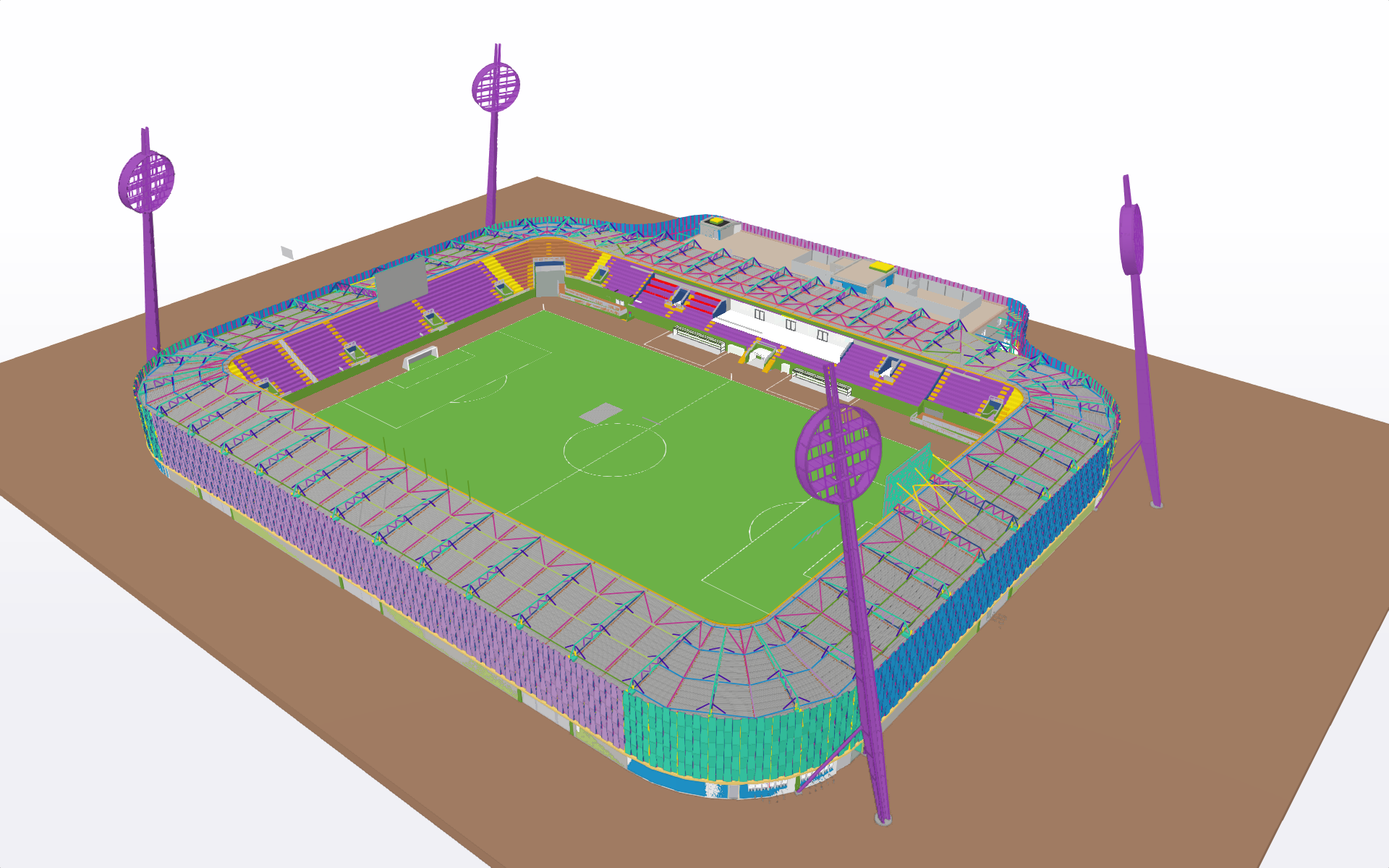
Stadion byl již ve studii rozdělen do tří základních částí.
První:
Severní, východní a jižní tribuny jsou propojené v rozích přechodovými obloukovými tribunami, tvoří je monolitické železobetonové konstrukce a pozinkovaná ocelová konstrukce zastřešení.
Druhá:
Západní tribuna je tvořena monolitickým železobetonovým třípodlažním skeletem se střešní nástavbou, monolitickou částí tribun a pozinkovanou ocelovou konstrukcí zastřešení.
Třetí:
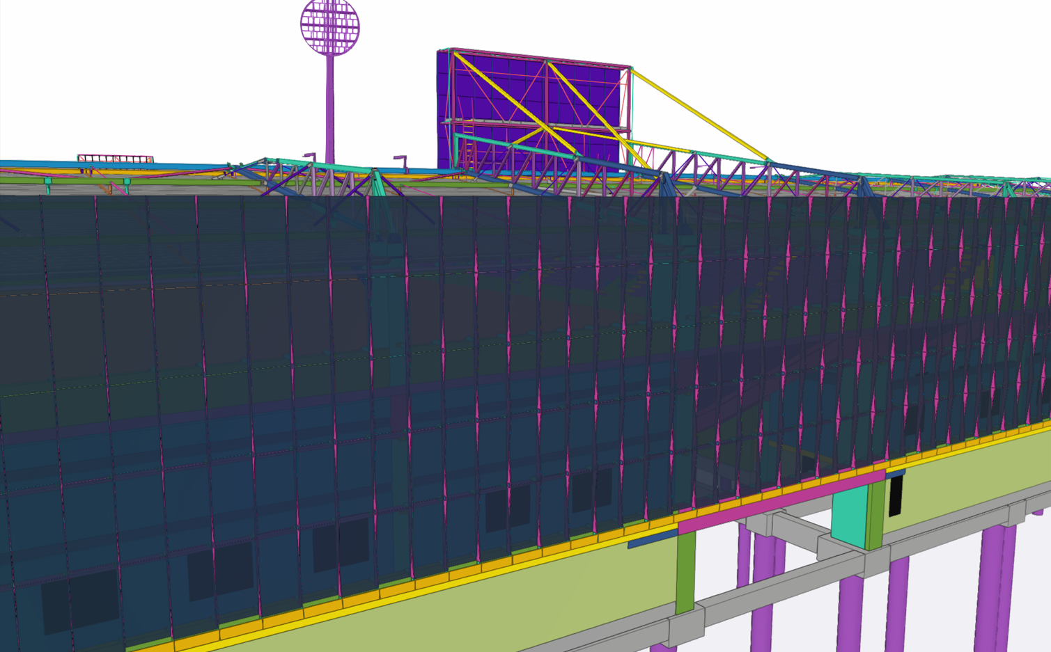
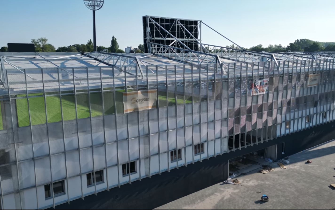
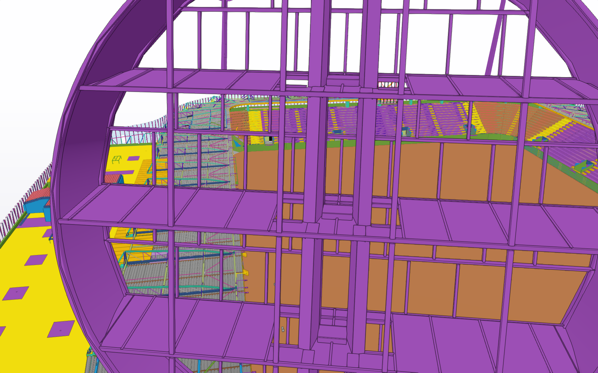
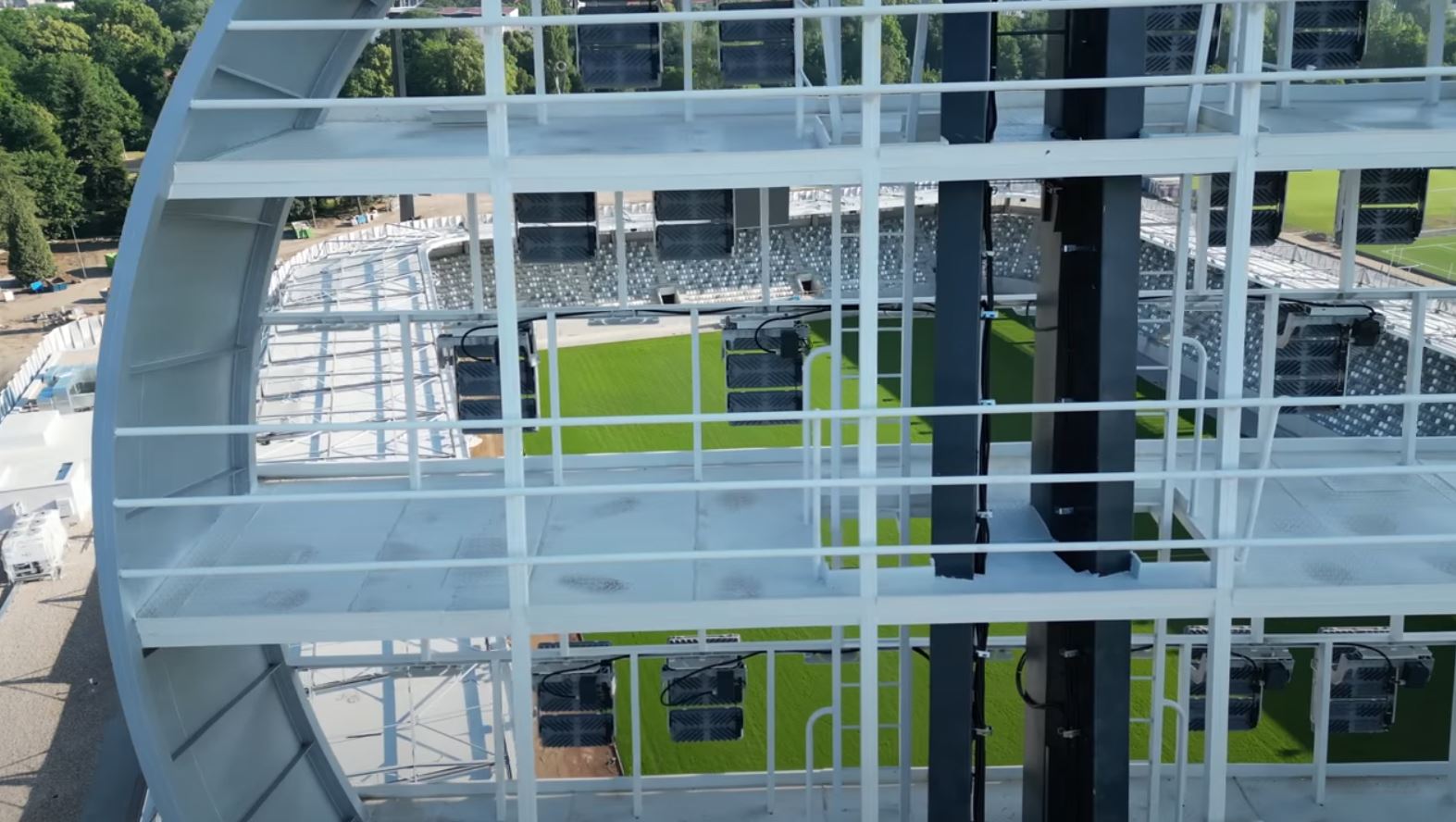
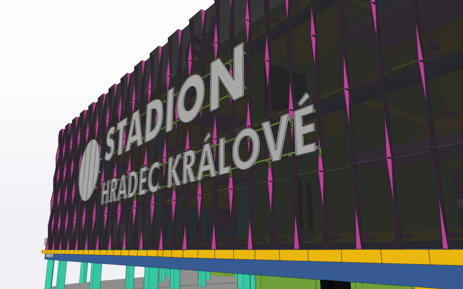
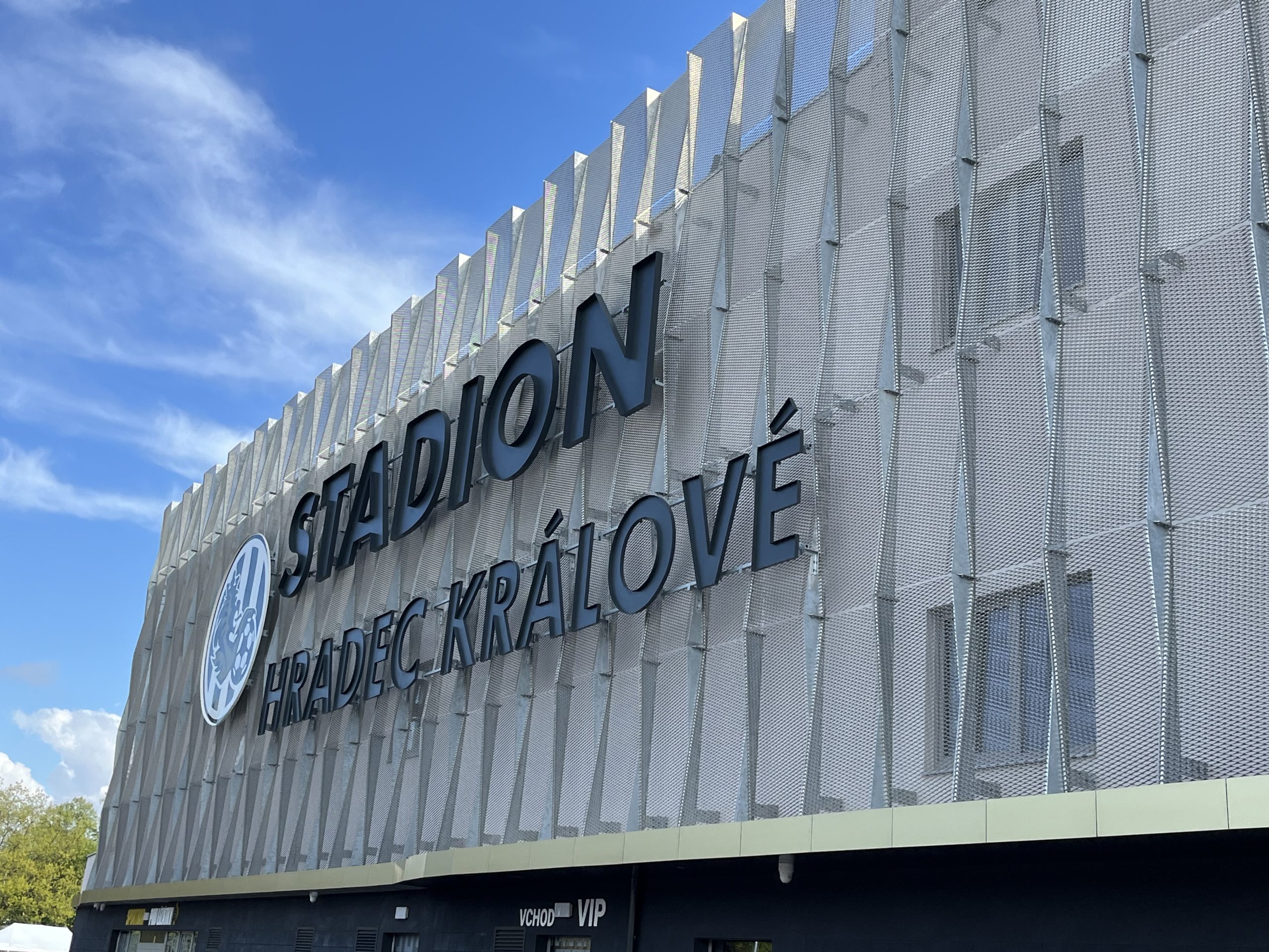
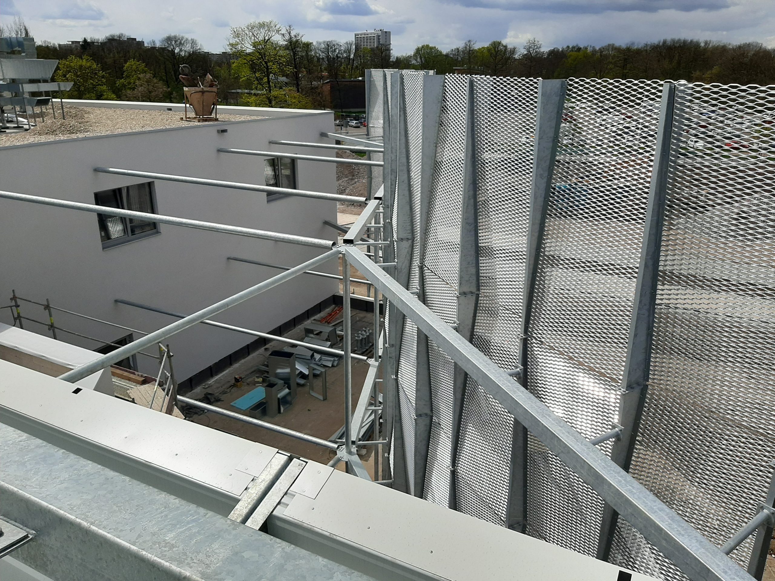
Fasáda po obvodu stadionu byla navržena ze systému pozinkovaných sloupků a vodorovných prvků. Výplň tvoří tahokov.
PRÁCE S VYUŽITÍM SYSTÉMŮ TRIMBLE:
A) Firma Geodézie Východní Čechy spol. s r. o. použila nivelační přístroje pro přesnou nivelaci Trimble DiNi03
B) Software Trimble Bussines Center byl firmou Geodézie Východní Čechy spol. s r. o. využit k:
1) k výpočtu veškerých kubatur zemních prací na stavbě – data byla z pravidla pořizována pomocí letecké fotogrammetrie (z UAV) a vyhodnocována z mračen bodů díky velké členitosti v místě stavby.
2) K výpočtu nivelačních pořadů, zaměřených pomocí výše uvedeného přístroje Trimble DiNi03
3) K porovnání zaměřených výšek na stavbě a digitálních modelů terénu, které byly součástí projektu stavby (např. pro kontrolu pláně okolních komunikací i hrací plochy)
4) Pro úpravu, zobrazení, vyhodnocení a přípravu digitálních modelů terénu plání, tak aby bylo možno data z projektu co nejefektivněji přenést do terénu = tyto modely následně nahrány do totální stanice a hodnoty z DMT byly vytyčeny přímo v terénu.
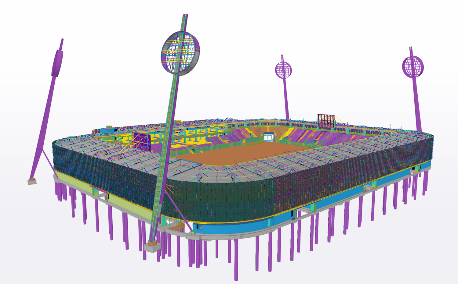
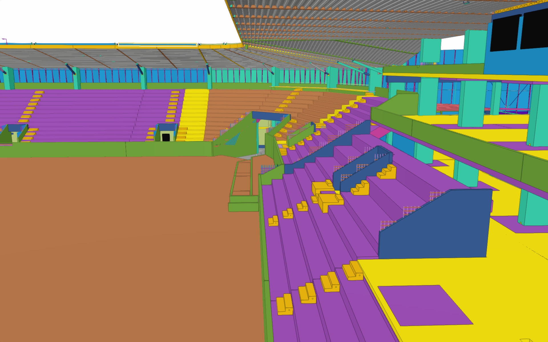
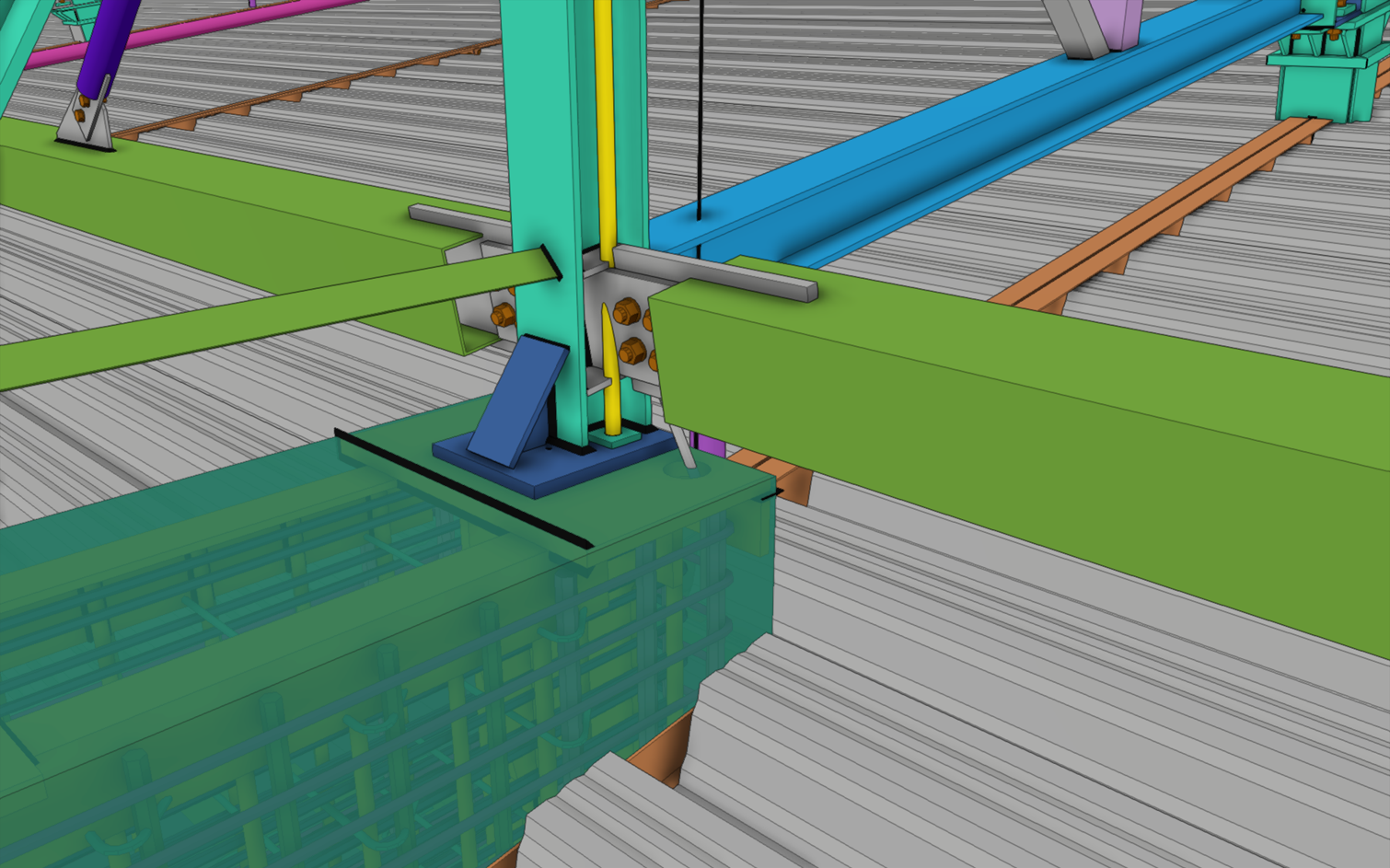
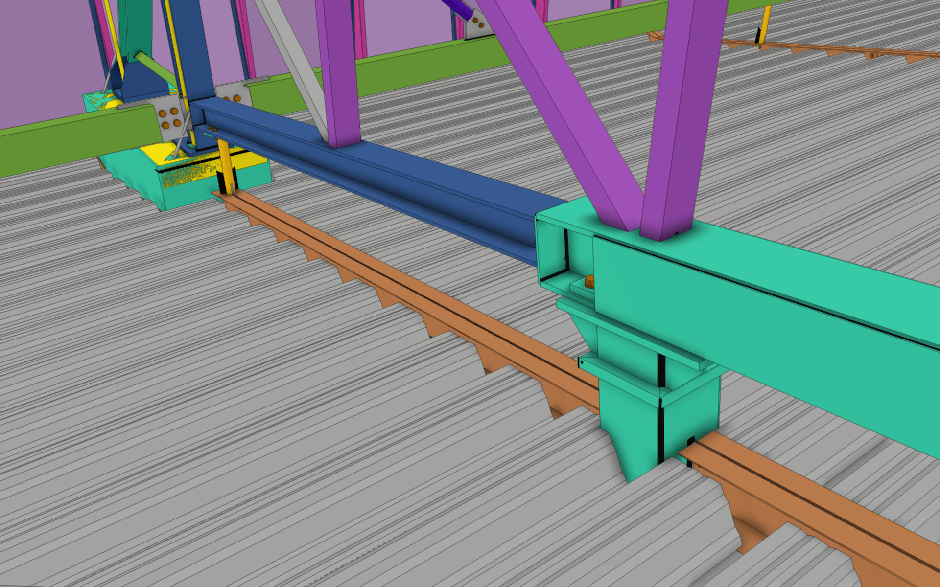
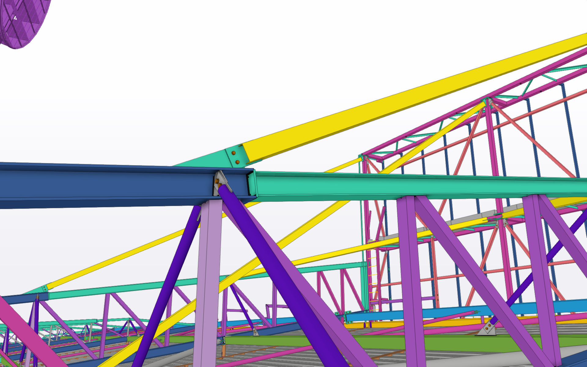
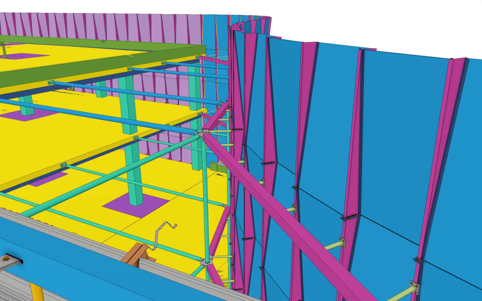
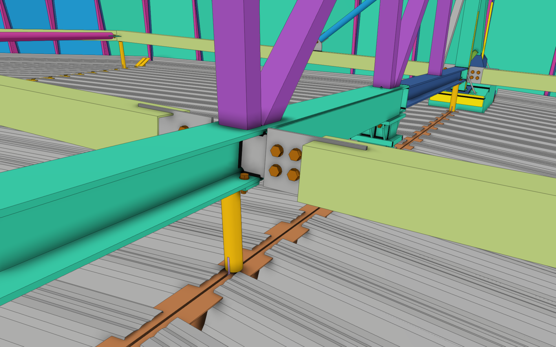
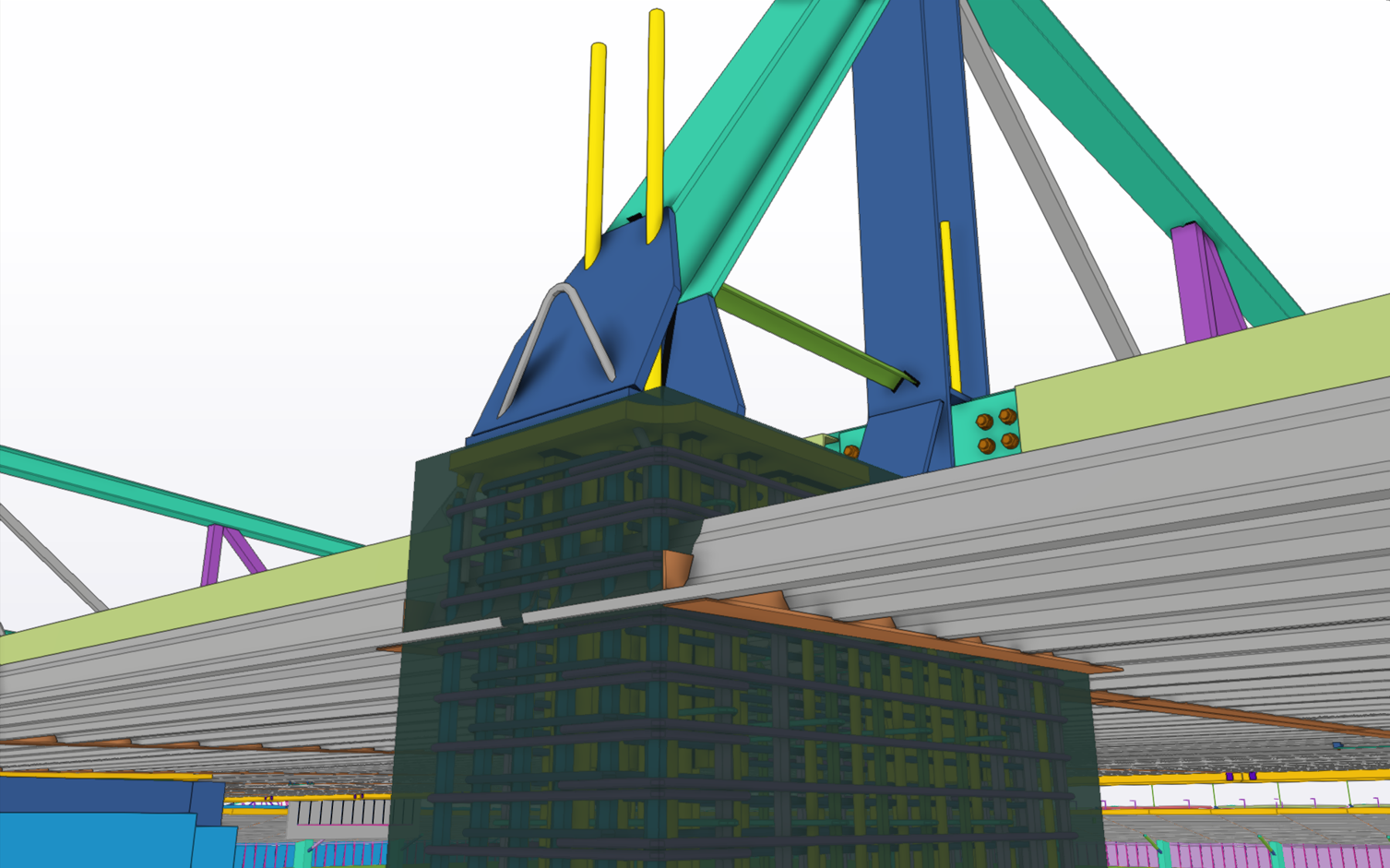
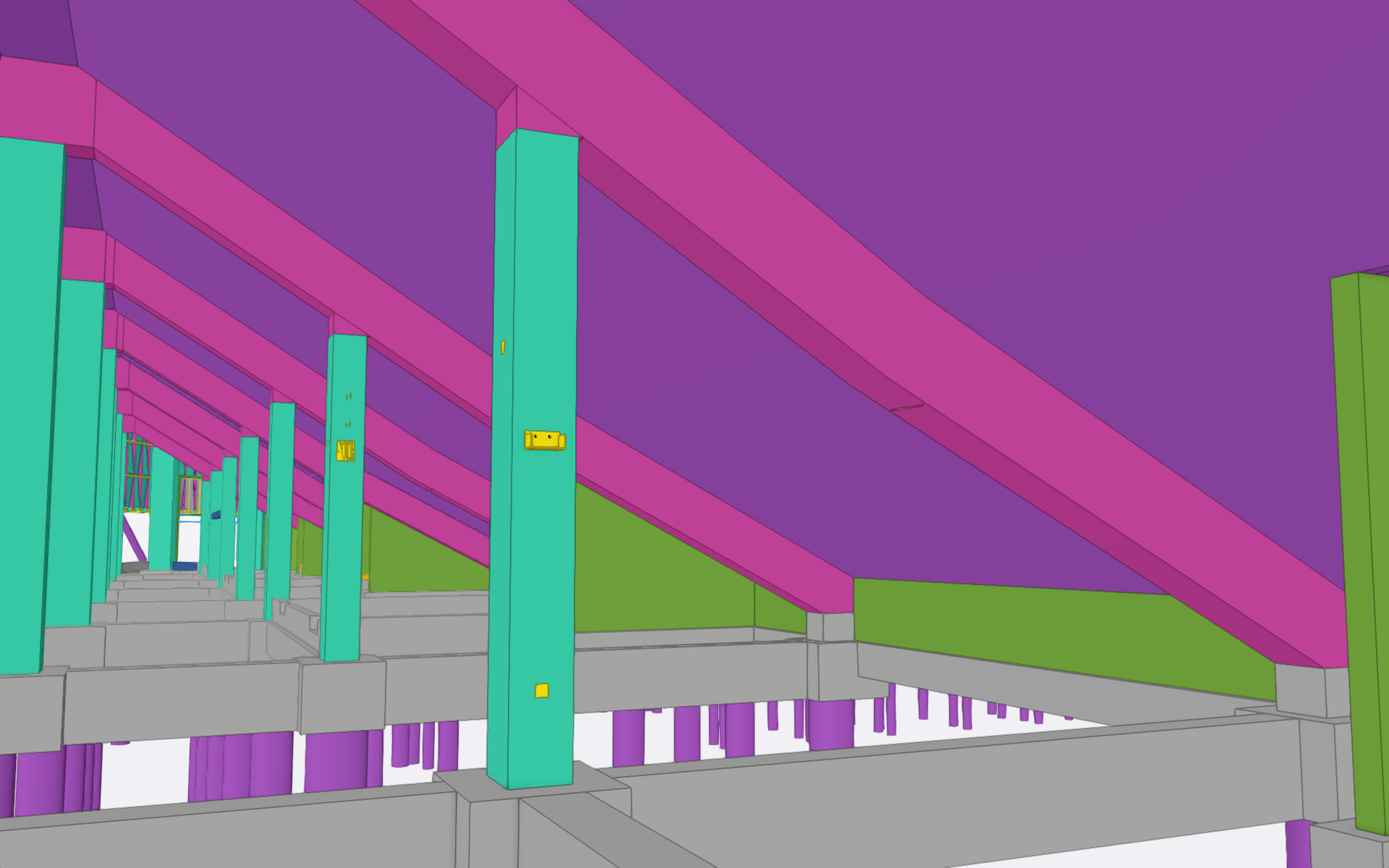
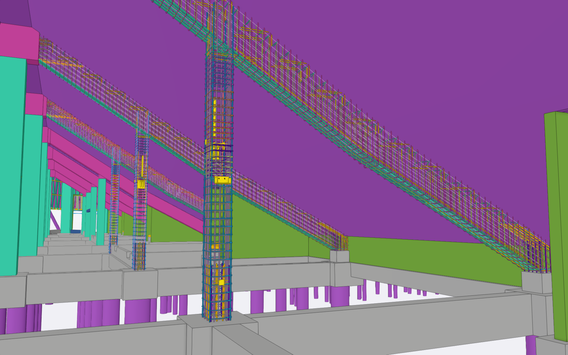
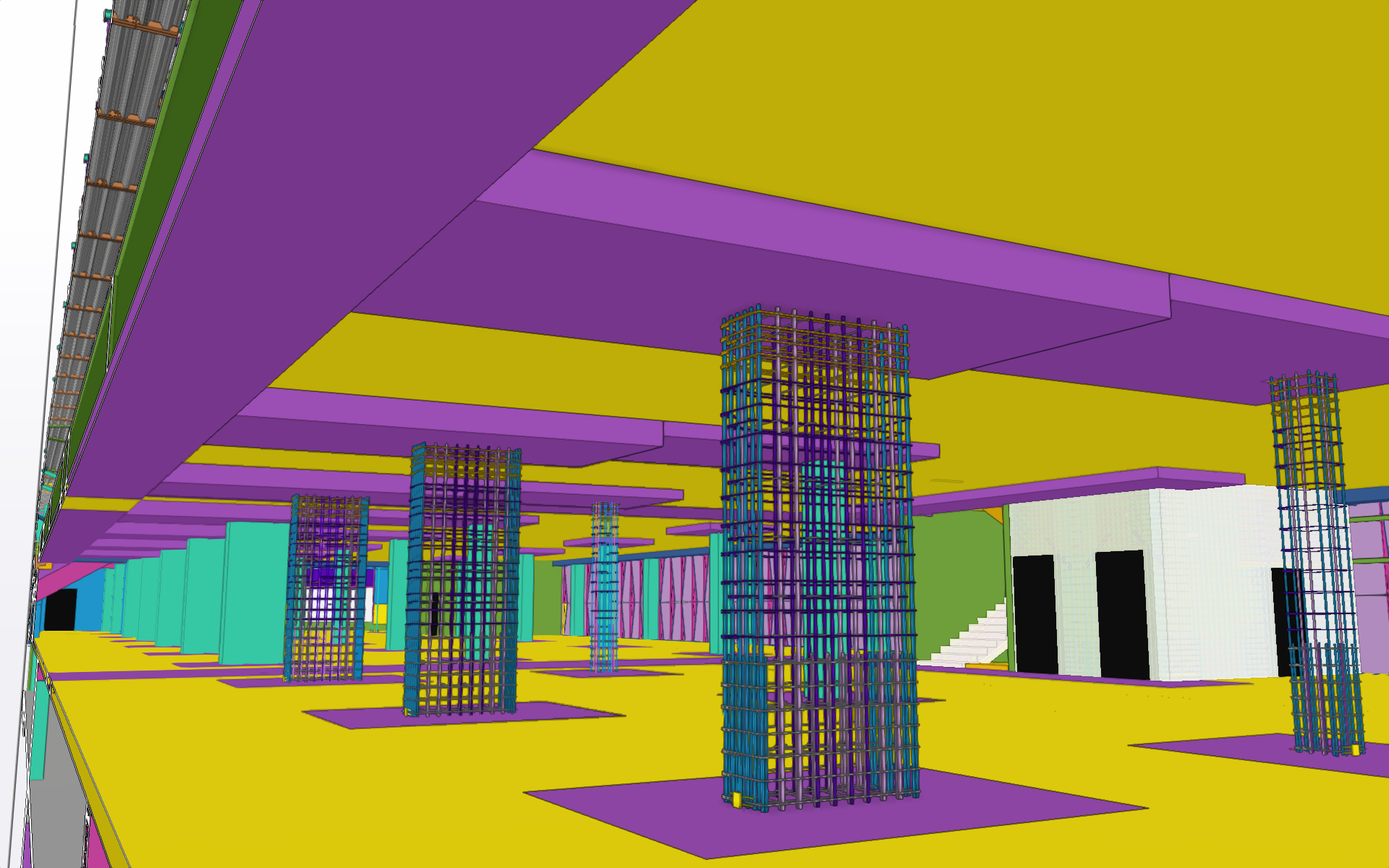
C) Ocelové i železobetonové konstrukce byly modelovány v programu TEKLA Structures firmou SKÁLA & VÍT, s.r.o. v jednom společném modelu. Díky tomu byla zajištěna koordinace ocelových a železobetonových konstrukcí v místě napojení na sebe.
Zpracovávané stupně dokumentace:
1) Změna stavby před dokončením
2) Prováděcí projekt
3) Výrobní a montážní dokumentace Ocelových konstrukcí
4) Dodavatelská dokumentace železobetonových konstrukcí
5) Dokumentace skutečného provedení
D) Program Trimble Connect byl použit k vzájemné koordinaci profesí využívajících 3D modely.
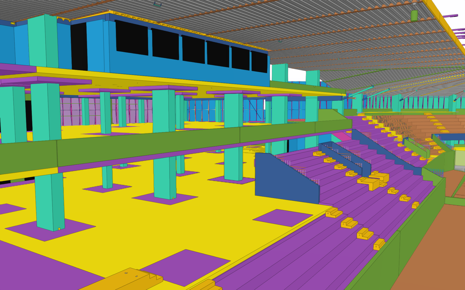
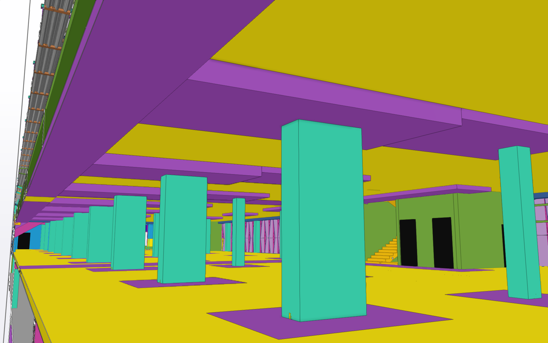
ŽELEZOBETONOVÉ KONSTRUKCE
Založení
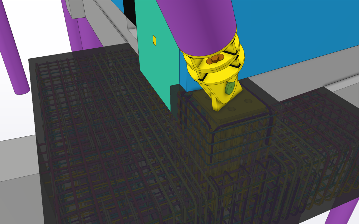
Na základě inženýrsko-geologického průzkumu bylo zvoleno založení na hlubinných vrtaných pilotách. Rozmístění pilot vychází z uspořádání horní nosné konstrukce. Piloty jsou opatřeny monolitickými železobetonovými hlavicemi, které jsou propojené monolitickými železobetonovými pasy pro přenos vodorovných sil a v místech založení zděných nosných obvodových stěn.
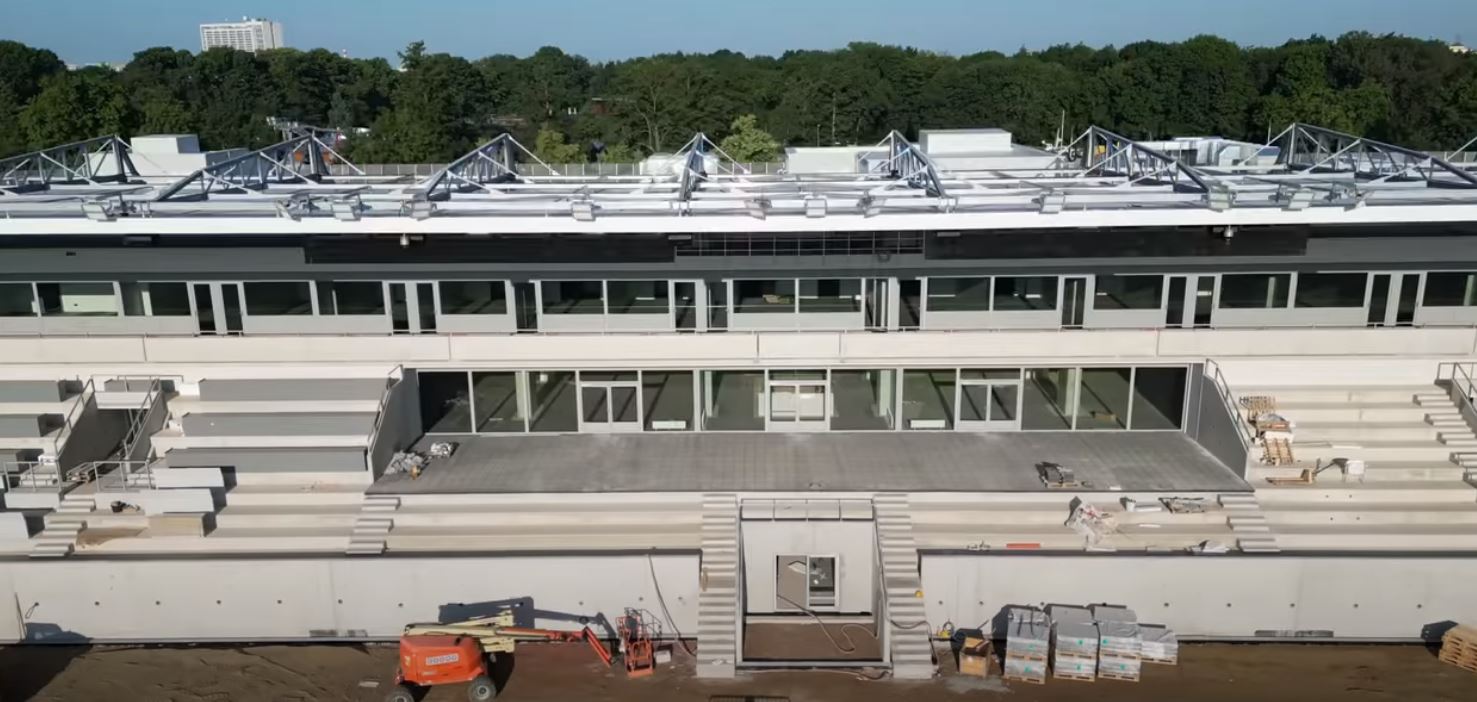
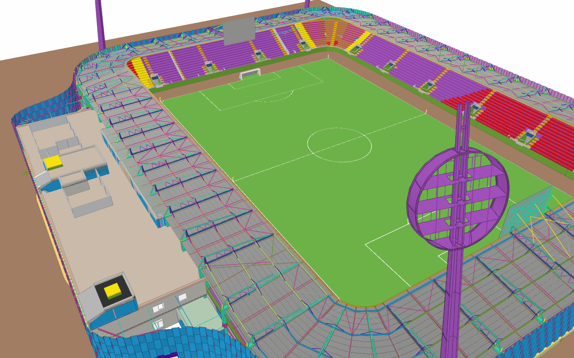
Západní tribuna
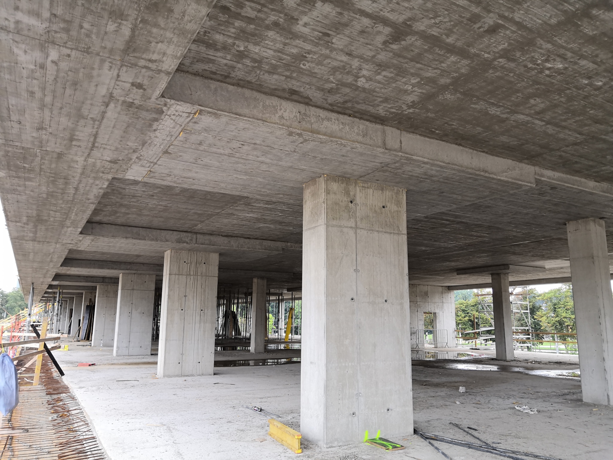
Monolitický železobetonový třípatrový skelet je tvořen svislými sloupy, ztužujícími stěnovými schodišťovými jádry a stropem zesíleným hlavicemi a plochými průvlaky. Samostatnou částí jsou venkovní VIP monolitické šikmé tribuny podepřené svislými sloupy a šikmými průvlaky. Základní modulový systém sloupů je v podélném směru 8,0m, v příčném směru 5,8m + 7,5m + 5,7m + 5,1m.
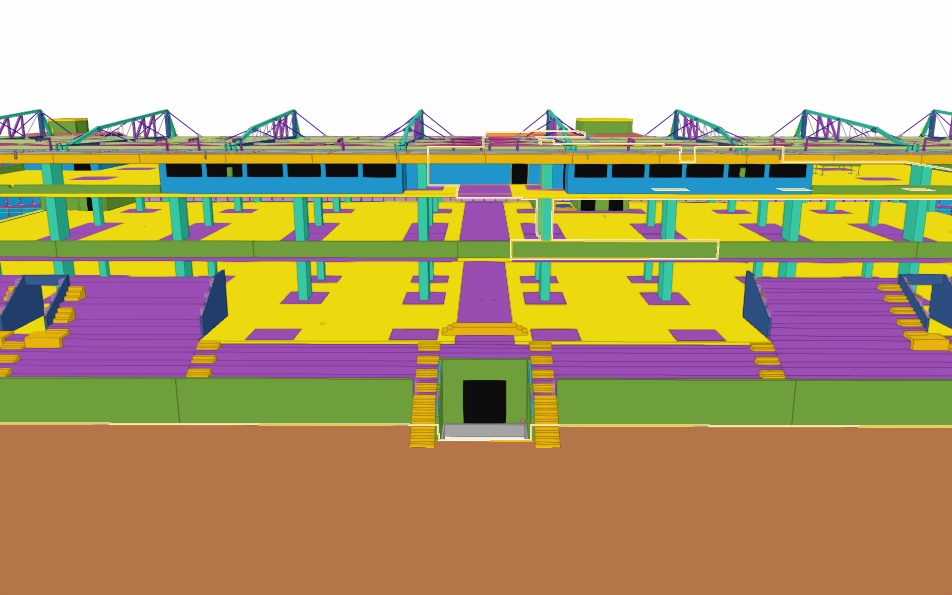
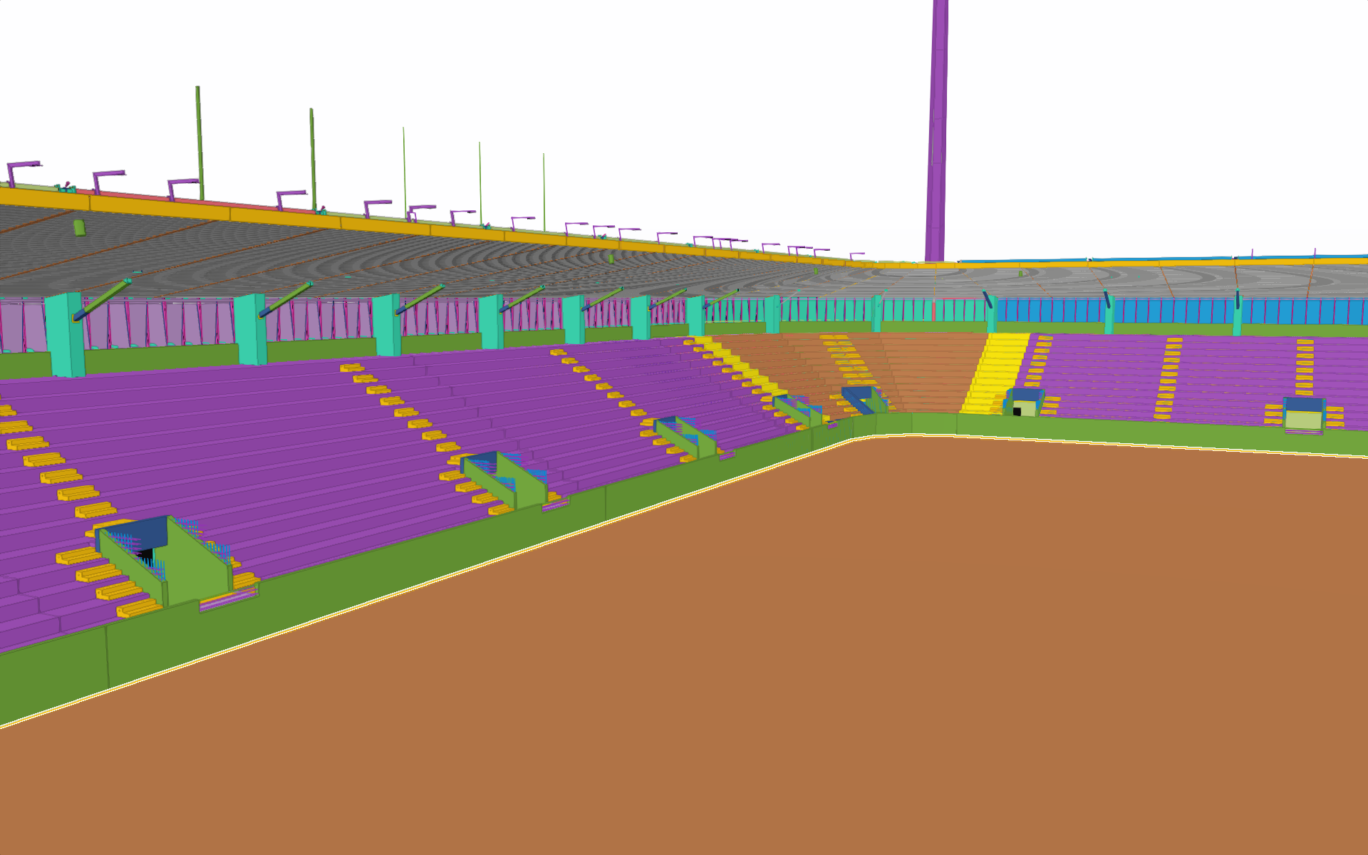
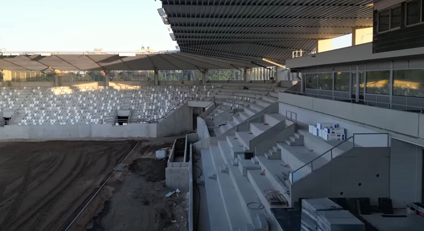
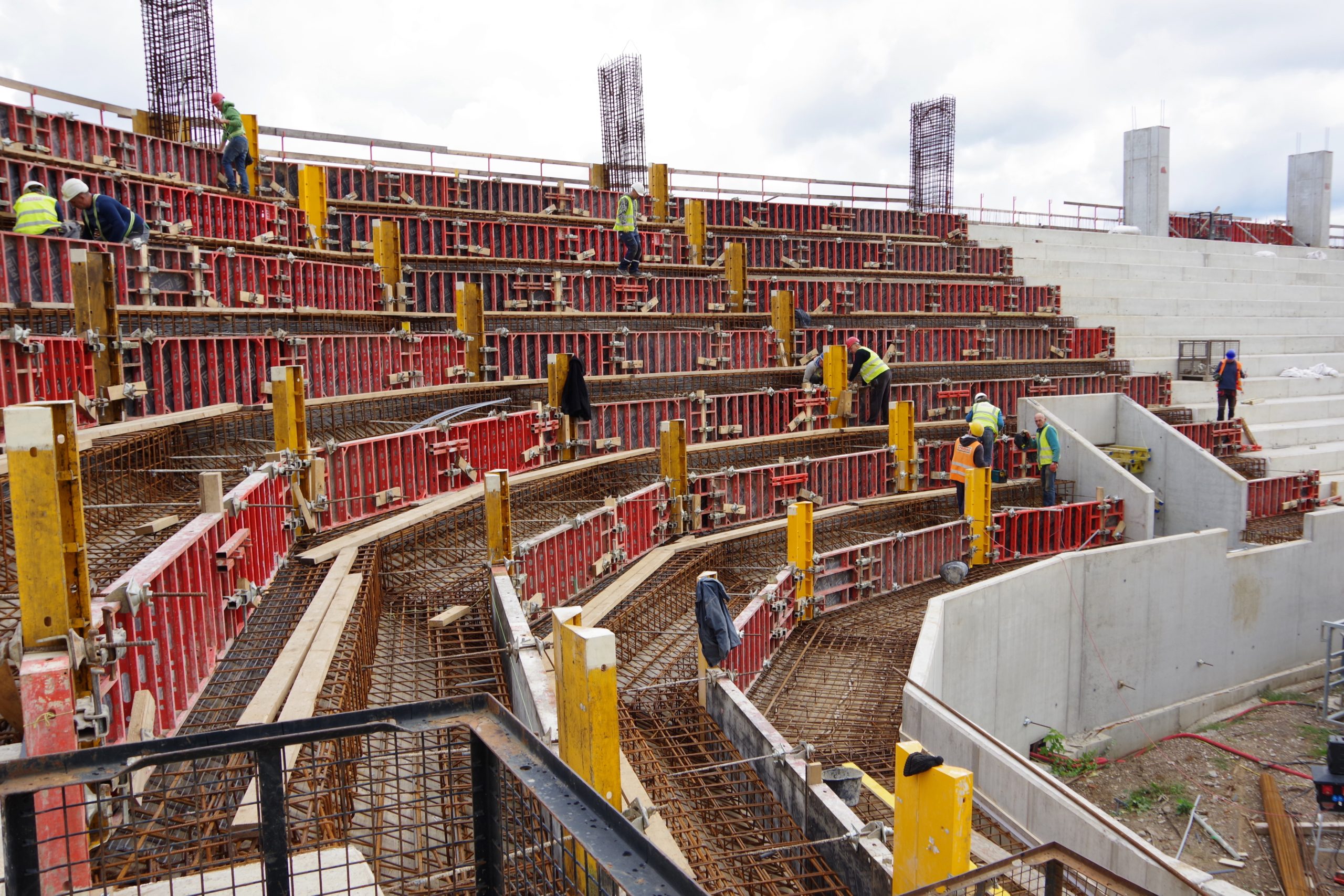
Severní, východní a jižní tribuna
Konstrukce tribun je v příčném směru tvořena monolitickým železobetonovým rámem ze tří sloupů a šikmého průvlaku. Na rámech je podélně uložena monolitická železobetonová konstrukce šikmých tribun tvaru stupňů, která je rozdělena na dilatační celky. V každém druhém poli jsou umístěny „moongaty“ – monolitické železobetonové stěny se schodištěm. Modulové osy příčných rámů jsou vzdálené 9,6m na východní tribuně a 10,1m na severní a jižní tribuně.
Po celém obvodu jsou pod tribunami vestavky se zázemím tvořené zděnými nosnými stěnami a monolitickým železobetonovým stropem.
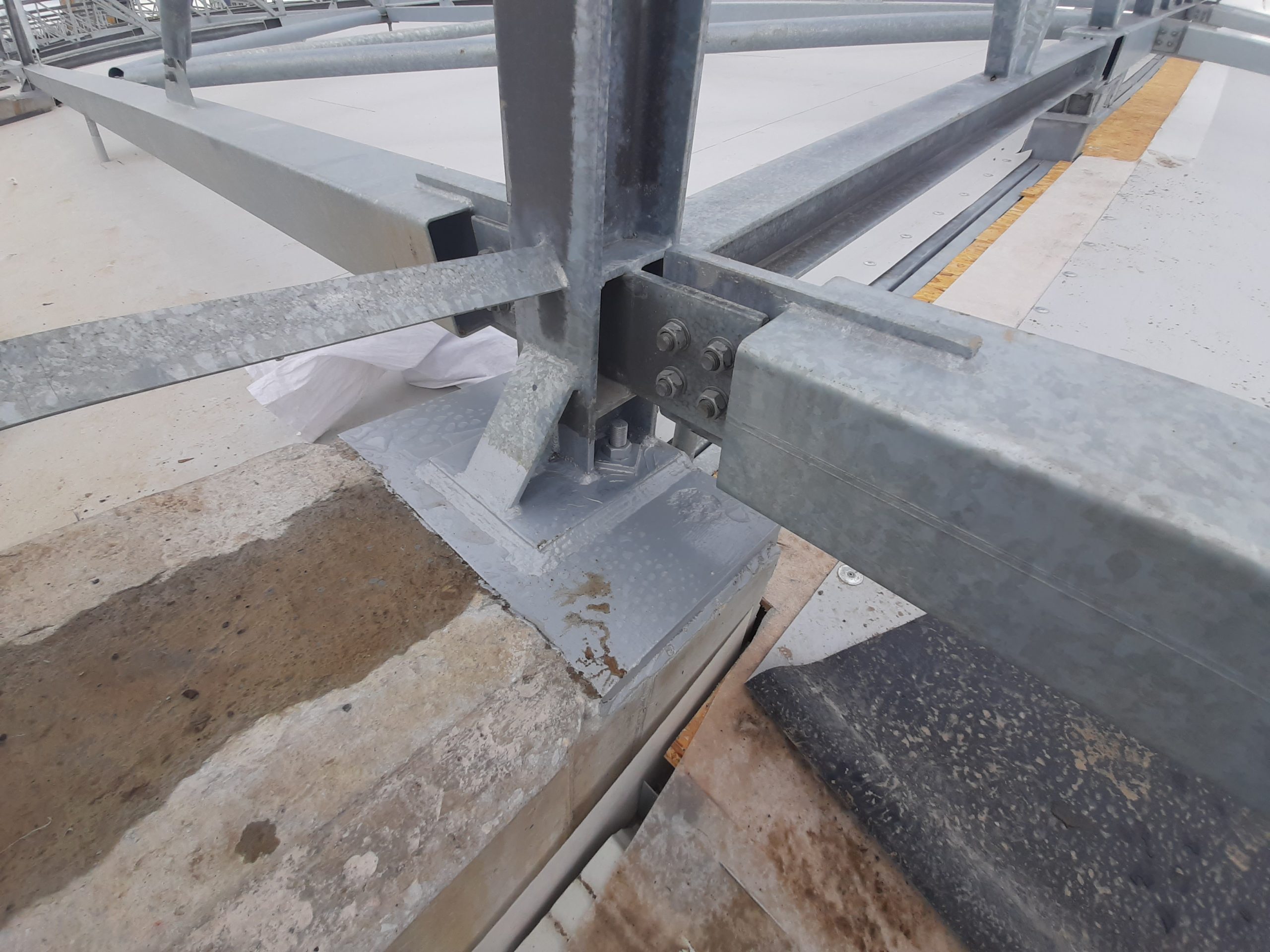
OCELOVÉ KONSTRUKCE
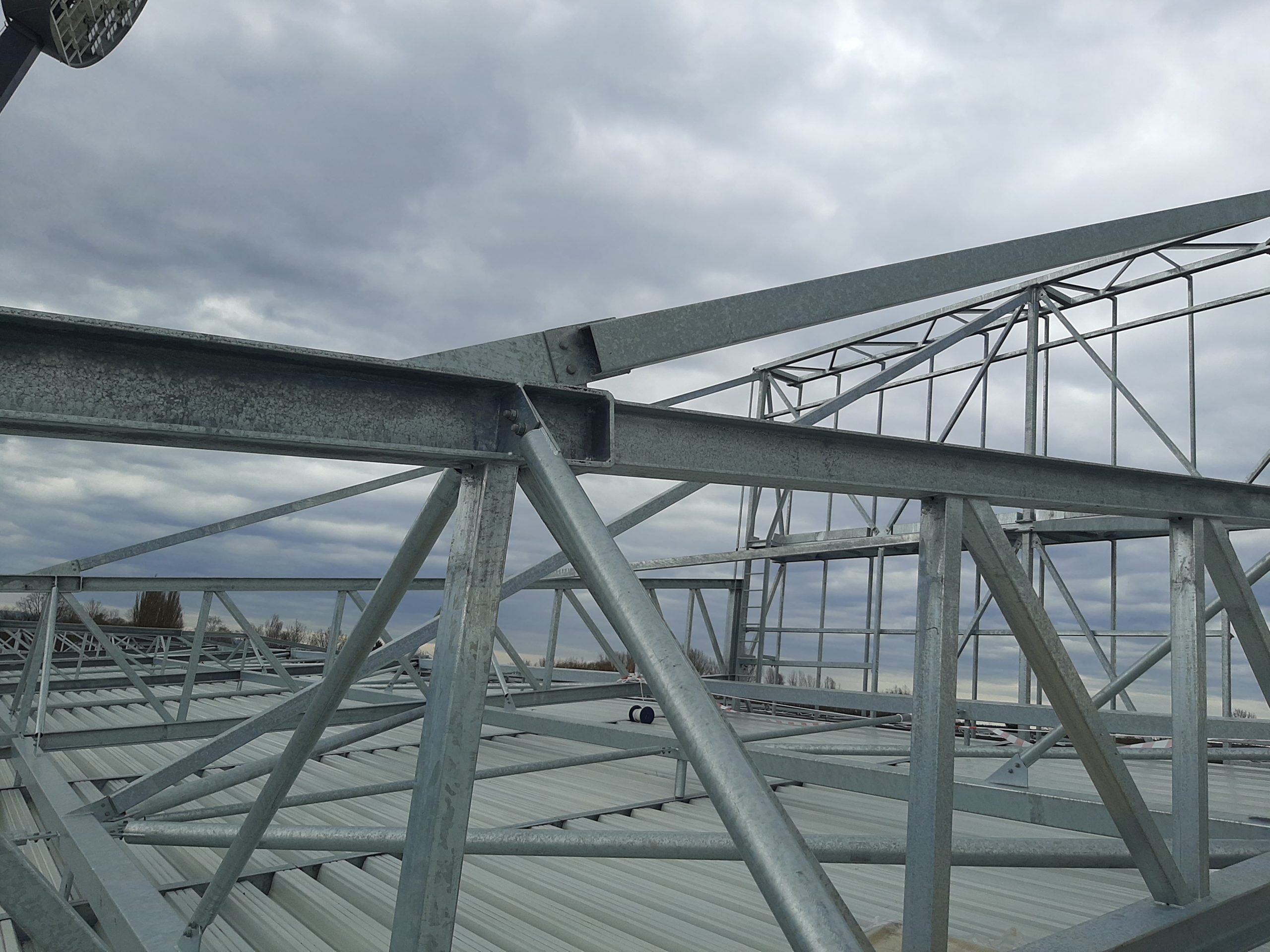
Konstrukce zastřešení
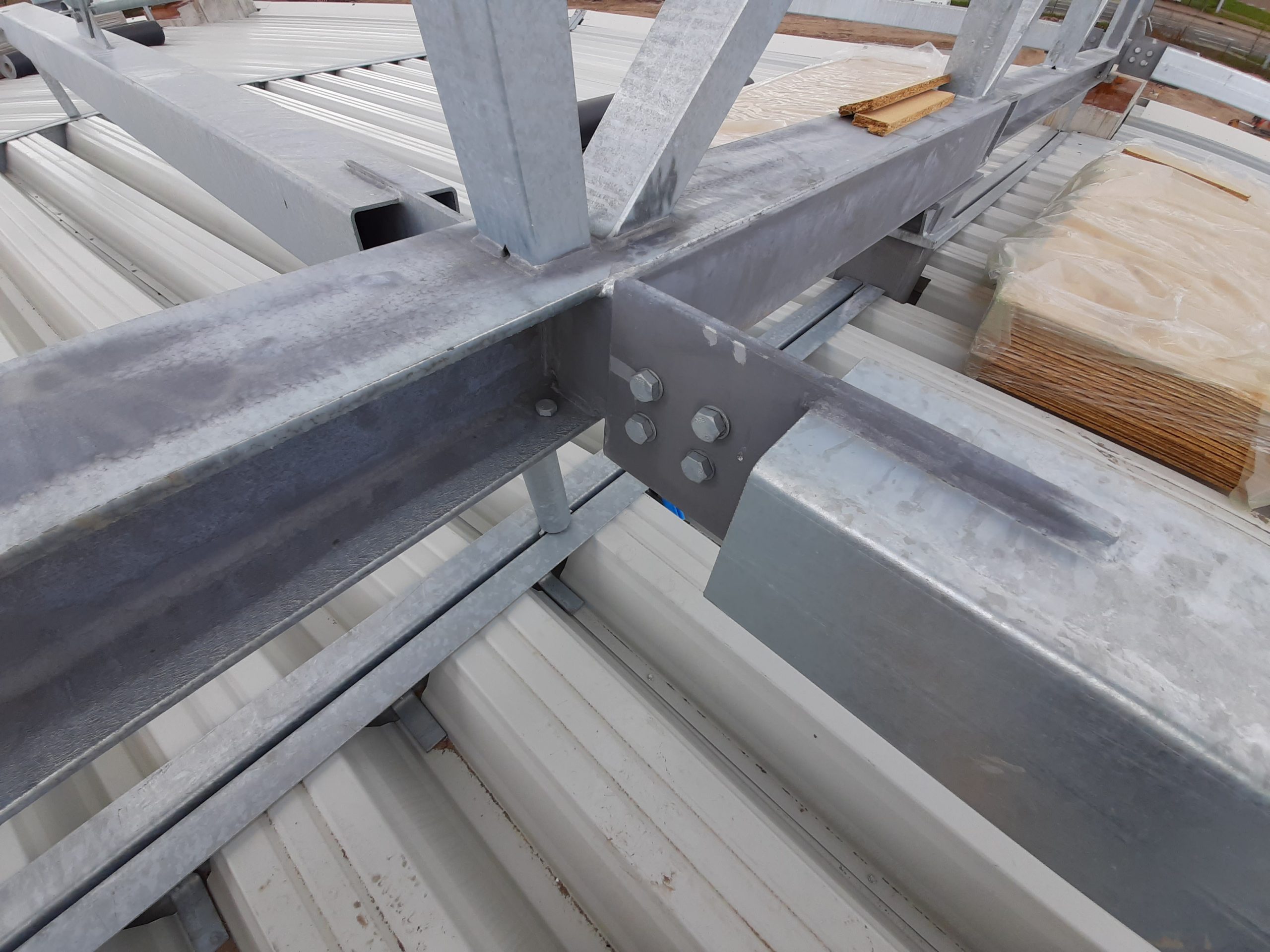
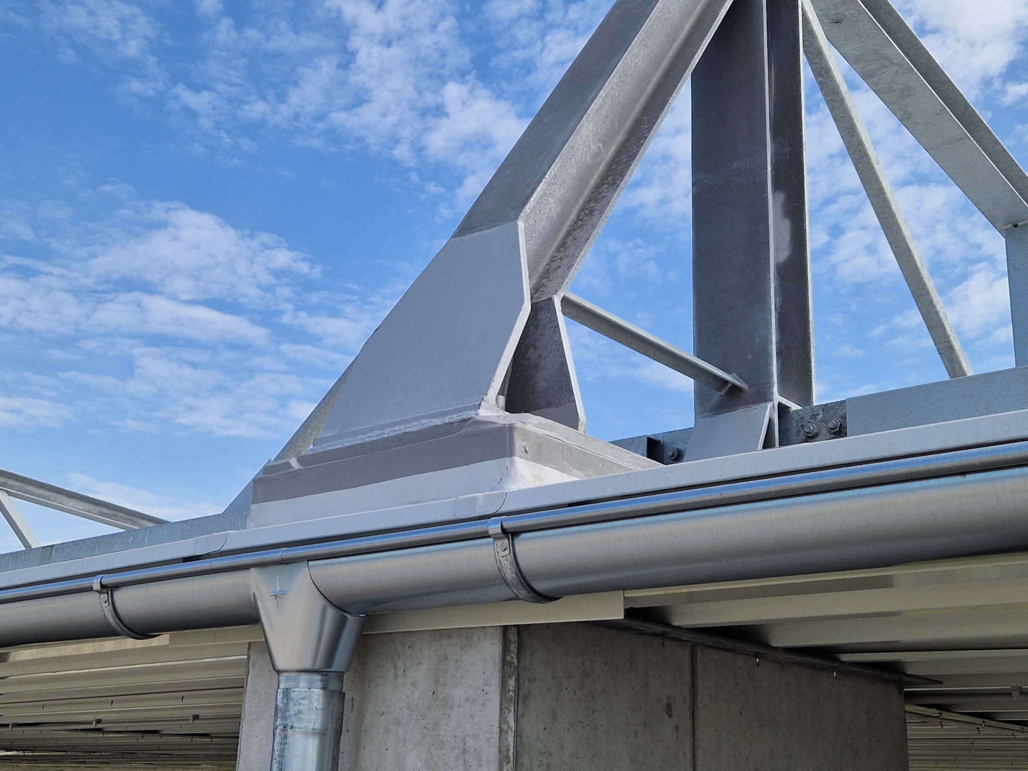
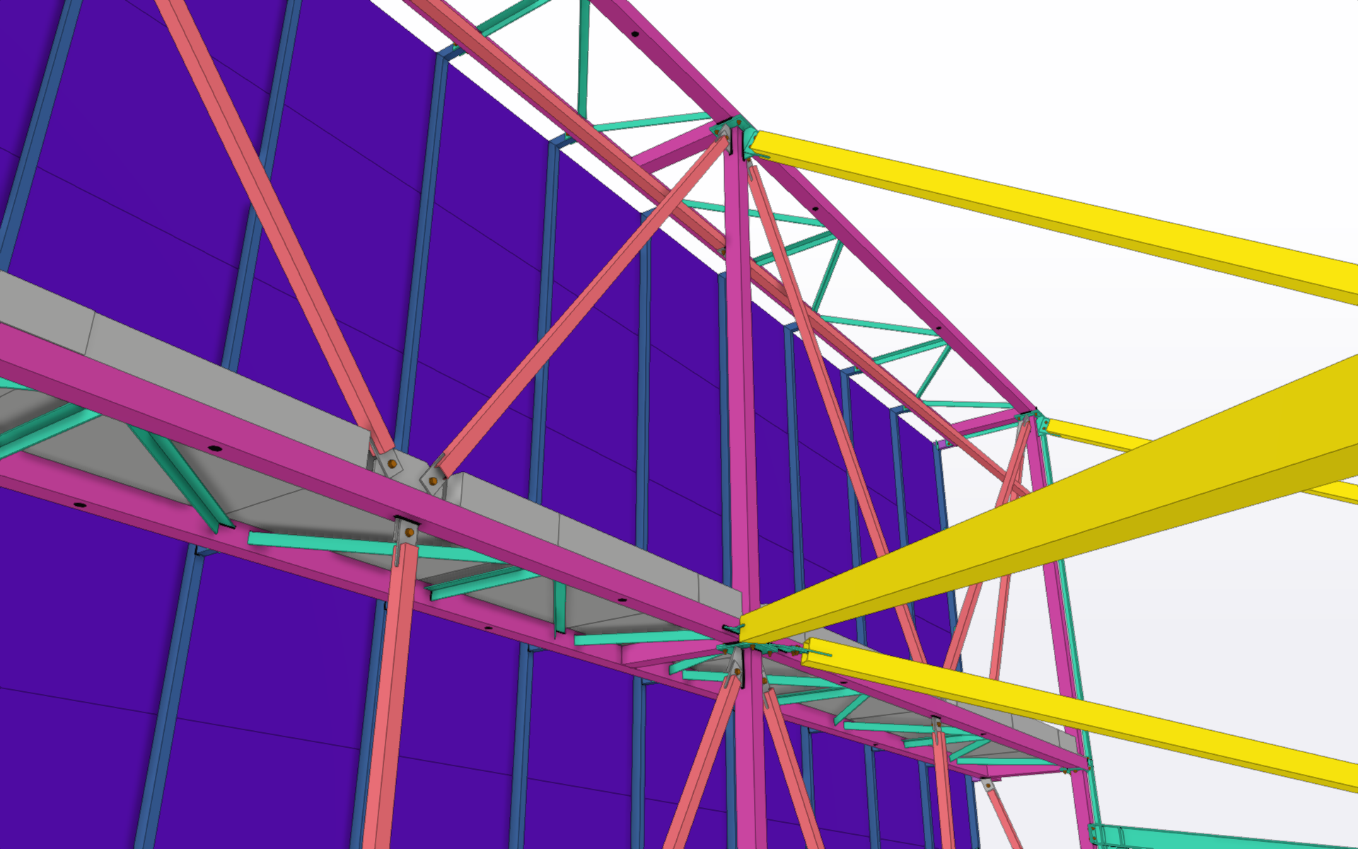
Hlavním nosným prvkem ocelového zastřešení tribun jsou pozinkované příhradové nosníky s vyložením cca 14 m jednostranně vykonzolované z hlavy monolitických ŽB sloupů. Vazníky jsou svařeny z válcovaných průřezů tvaru H a diagonály se svislicemi z uzavřených obdélníkových a čtvercových průřezů. Pozinkovaný vazník má tvar ležatého čtyřúhelníku, jehož výška je největší nad hlavou ŽB sloupu, na kterou je připevněn, a na konci vyložení je výška nejmenší. Nad sloupem je výška cca 1 700 mm. Nestejná výška základen umožní vyspádování střešní roviny umístěné pod spodním pasem vazníku směrem k vnějšímu obrysu tribun.
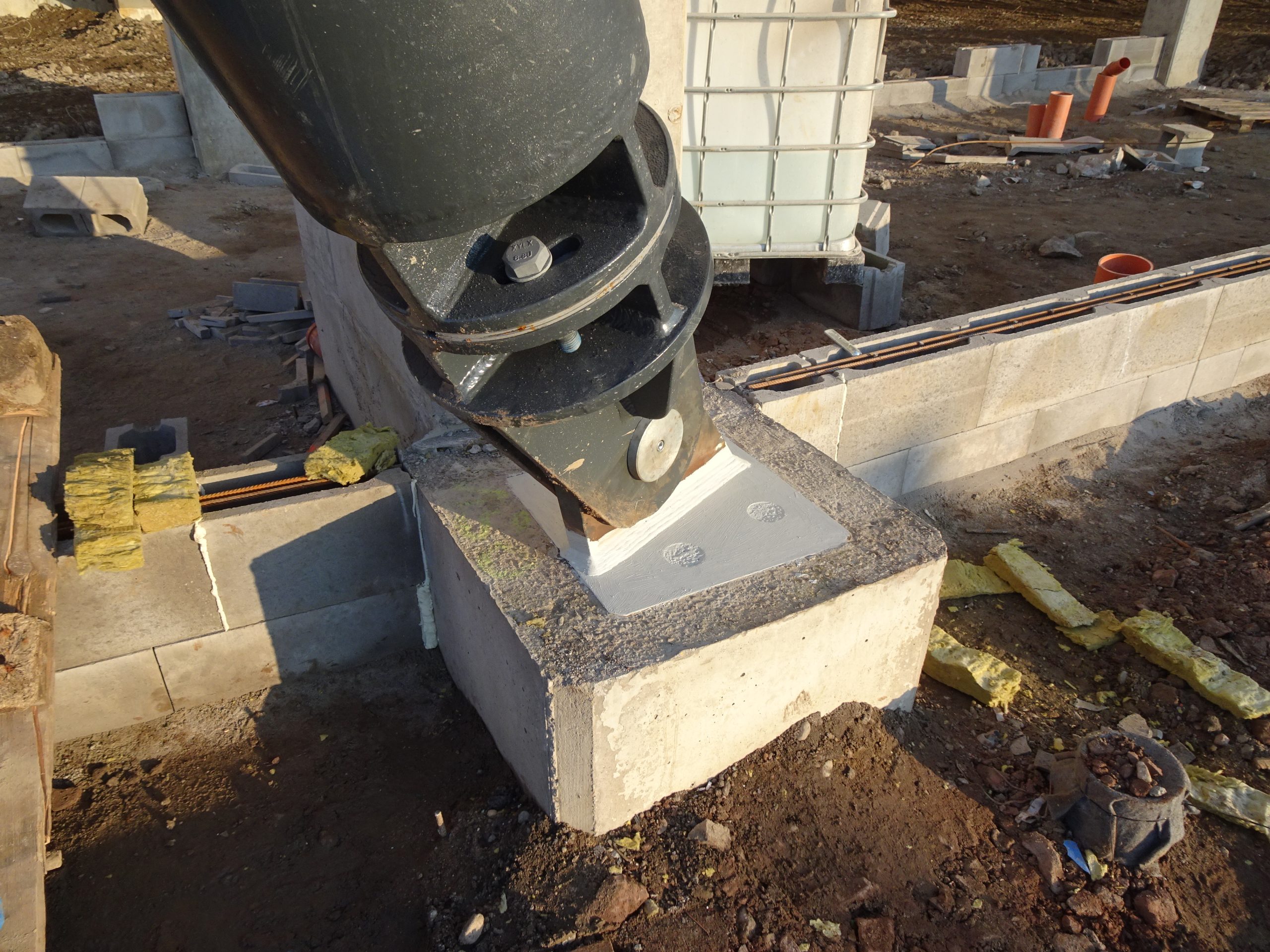
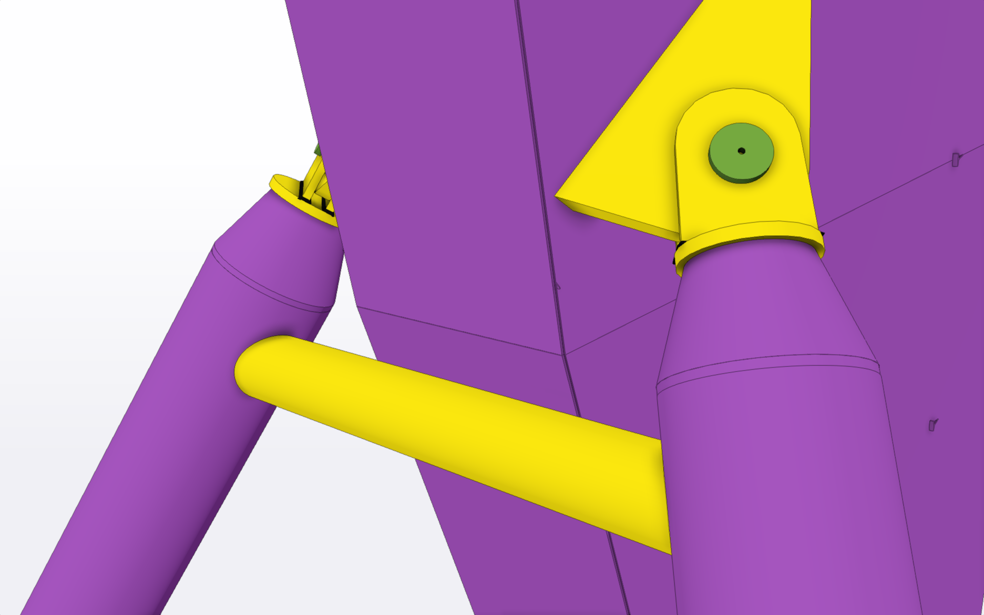
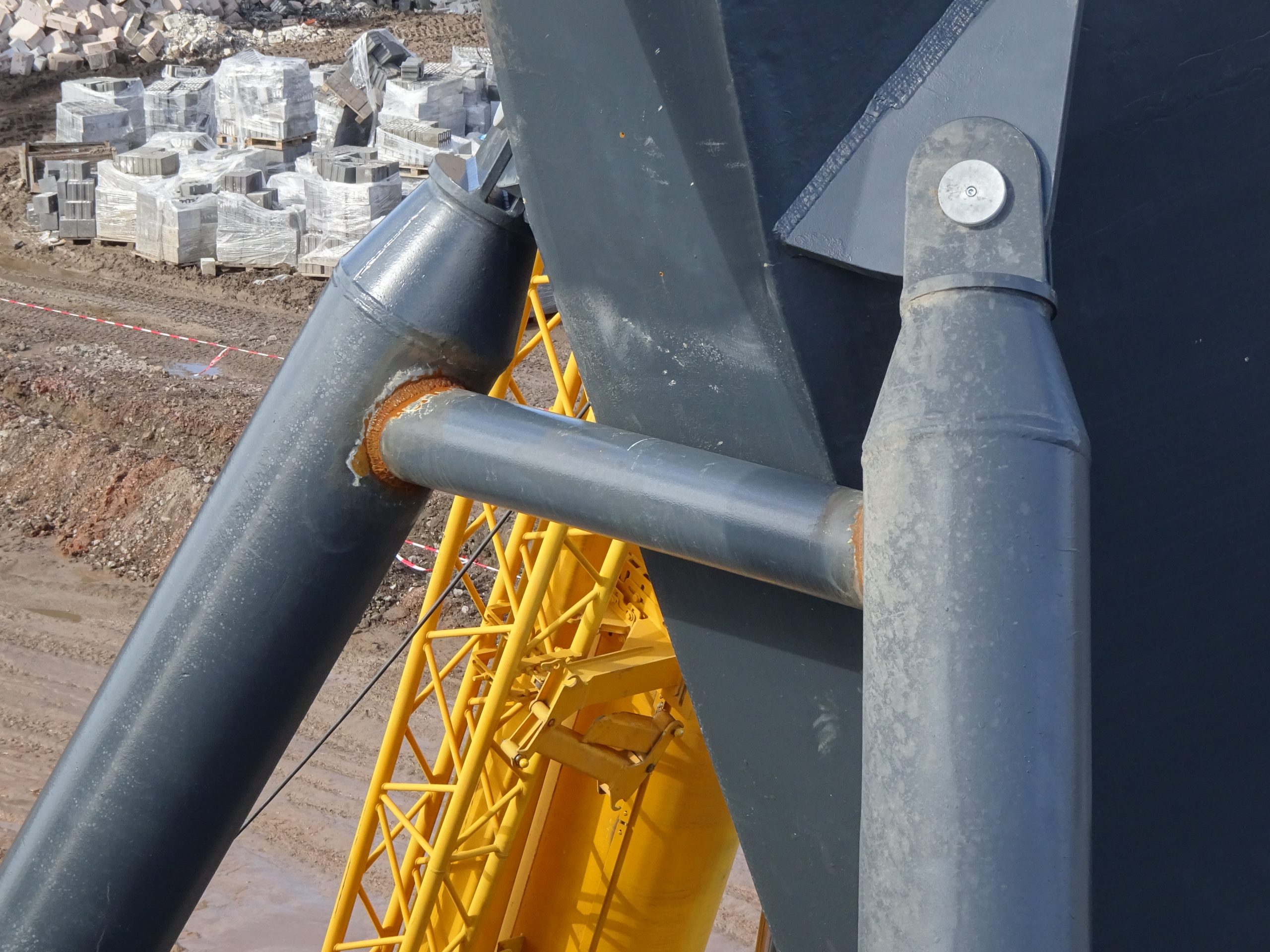
Pozinkované vazníky severní, východní a jižní tribuny jsou podepřeny pozinkovanými vzpěrami ze čtvercových průřezů. Vzpěry podepírají pozinkované vazníky přibližně v jedné pětině délky spodního pasu a cca 2 m pod vrcholy sloupů.
Pozinkované vazníky západní tribuny jsou stejného systému. Odlišný je pouze sklon střechy a absence vzpěr, kdy výška nad terénem v místě maximálního vyložení je zachována a díky menšímu spádu je dosaženo vyšší úrovně uložení na betonové sloupy.
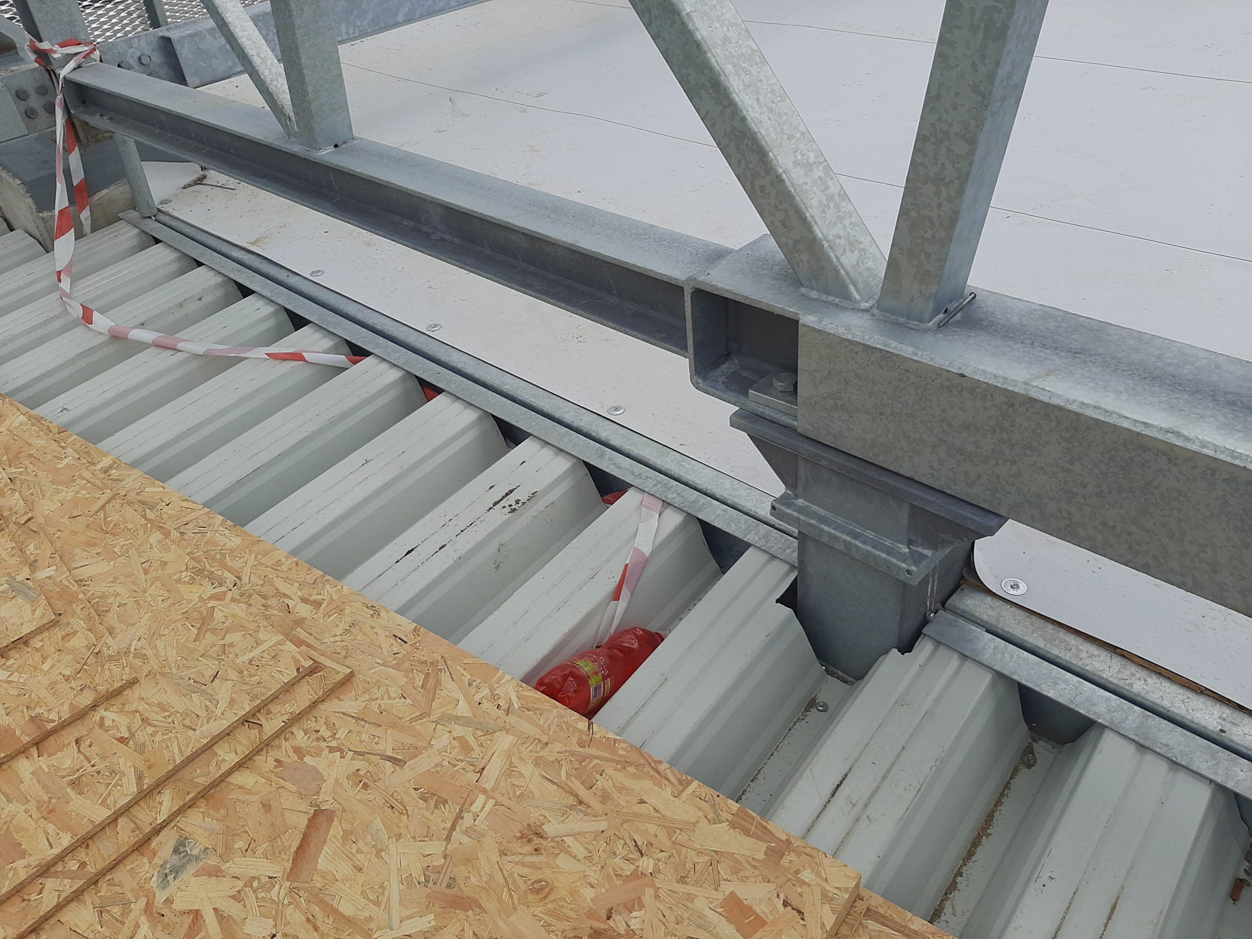
V úrovni spodního pasu vazníků jsou připevněny pozinkované vaznice z válcovaných průřezů čtvercového tvaru a ve vzdálenosti 2 m od vazníku jsou vyvěšeny z úrovně horního pasu táhly z kruhových trubek. Krajní pozinkovaná vaznice u konce vyložení není vyvěšená, ale tvoří spojitý nosník. Přechodová pole u západní tribuny, kde dochází ke změně sklonu, jsou vytvořena pomocí zalomených pozinkovaných vaznic a šikmo uloženého pozinkovaného nosníku pro uložení pozinkovaných, lakovaných trapézových plechů.
Pod spodními pasy a uprostřed vaznic jsou připojeny konzoly z kruhových trubek, které nesou nosníky z dvojic průřezů U ohnutých z plechu orientovaných po spádu střechy. Do profilů nosníku jsou vsazeny trapézové plechy výšky 135 mm, které tvoří nosnou část střešního pláště. Na plechy jsou připevněny desky na bázi dřeva a hydroizolační fólie PVC.
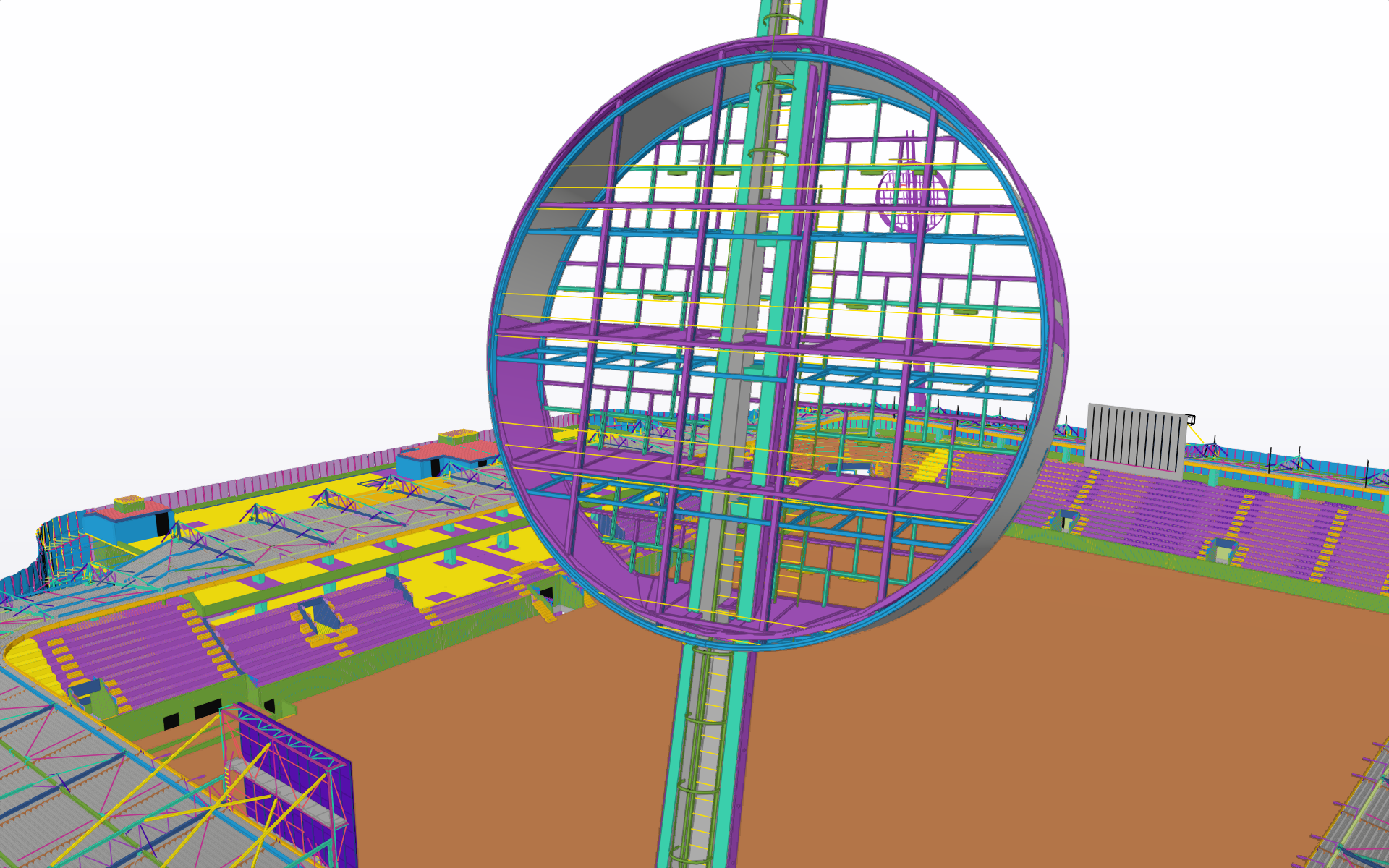
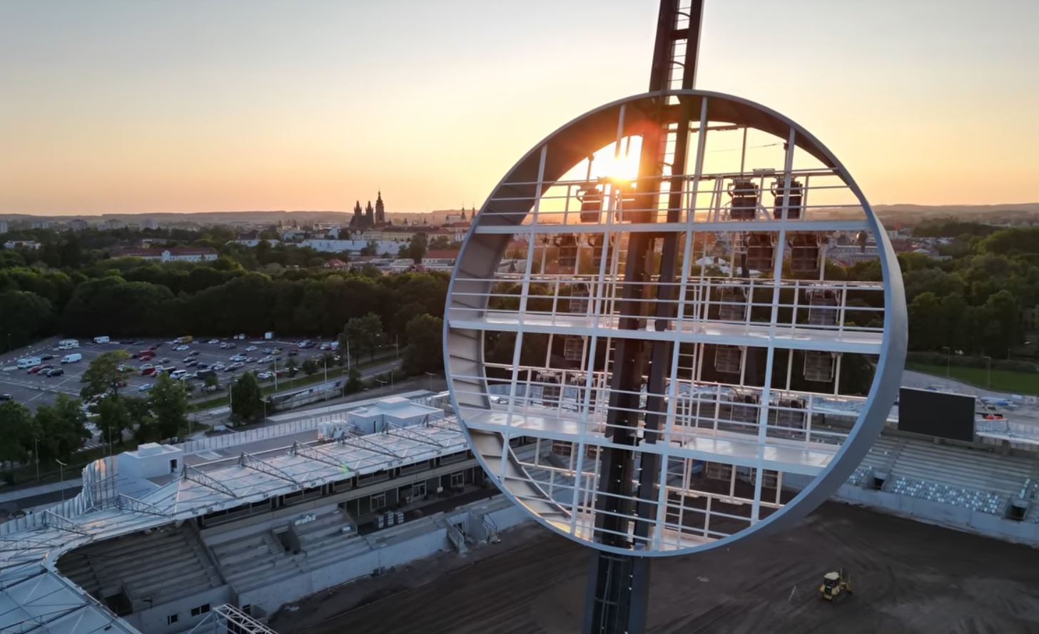
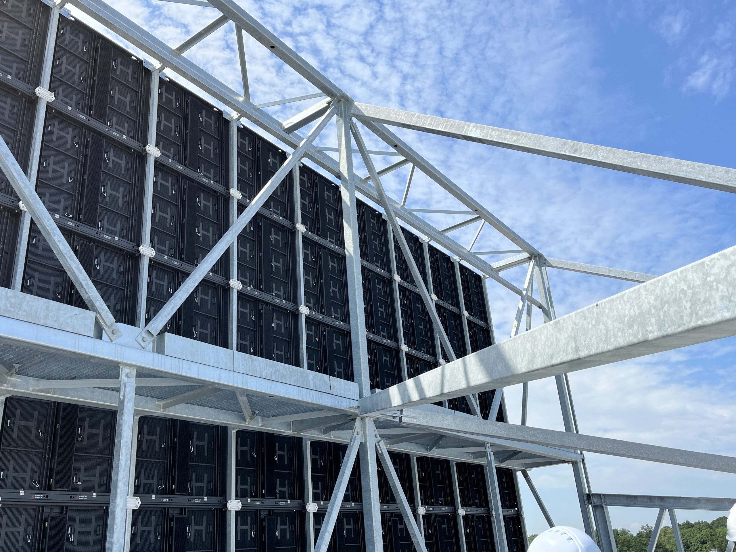
Za fotbalovými brankami na severní a jižní tribuně je na dva atypické vazníky s dalšími vzpěrami a ztužením, připevněna konstrukce pro upevnění obrazovky s rozměry cca 6,9 x 10,6 m.
Konstrukce fasád
Fasáda po obvodu stadionu je tvořena systémem sloupků průřezu T s proměnnou výškou stojiny, které jsou svařeny z plechů. Sloupky jsou připojeny v patě na obvodovou ŽB stěnu stadionu a dále se opírají ve dvou úrovních o tenkostěnné paždíky tvaru C, v jedné úrovni o lem tribunového nosníku a v jedné (horní) úrovni o válcovaný profil tvaru U. Poslední část sloupku tvoří převislý konec. Mezi sloupky jsou připevněny rámečky z úhelníků ohnutých z plechu, které nesou výplň z tahokovu s maximálním poměrem zaplnění 50 %.
Ostatní konstrukce
Schodiště, zábradlí, plošiny VZT, chlazení atd. jsou provedeny jako pozinkované ocelové konstrukce.
MULTIFUNCTIONAL FOOTBALL STADIUM HRADEC KRÁLOVÉ
• Investor: Statutory City of Hradec Králové
• Construction method: Design & Build
• Architect: Tomáš Vymetálek Architects
• Chief designer: ARCHaPLAN
• Construction: SKÁLA & VÍT
• Construction contractor: association of the Strabag, Geosan Grup, D&D Elektromont
• Capacity: 9300 spectators, all places covered, intended for sitting
• VIP space capacity: 500 seats
• Skybox capacity: 210 seats
• Start of construction work: August 2, 2021
• Approval: August 2, 2023
• First match: 5 August 2023
• Grand opening: September 3, 2023
• Interesting videos about stadium:
The Malšovická Arena was built in 2022 and 2023 on the site of the former All-Sports Stadium in Hradec Králové. It was already built in 1970, and fifteen years later the famous lollipops were added to it, which were preserved even for the new arena.
For several years, the historic stadium did not meet the standards of the first league, so it had to be replaced with a modern sanctuary. After the return of Hradec Králové to the top competition, the Votroci had to move to the Lokotrans arena in Mladá Boleslav for the 2021/22 and 2022/23 seasons. Here they had to wait until the construction of the new multifunctional arena was completed.
The construction of a modern multifunctional stadium in Malšovice was approved in March 2021, and the construction was undertaken by an association of companies Strabag, Geosan Group and D&D Elektromont.
The arena should be inaugurated on September 3, 2023, the construction cost 763 million CZK including VAT. The capacity of the arena will be 9,300 seats, making it one of the largest football stadiums in the Czech Republic.
PROJECT:
The stadium was already divided into two parts in the study.
The first part (north, east and south), connected at the corners by transitional arch stands, consists of monolithic reinforced concrete structures and a galvanized steel roofing structure.
The second (western) part consists of a monolithic reinforced concrete three-story skeleton with a roof structure, a monolithic part of the stands and a galvanized steel roofing structure.
The facade around the perimeter of the stadium was designed from a system of galvanized posts and horizontal elements. The filling consists of expanded metal.
WORKING USING TRIMBLE SYSTEMS:
A) The company Geodézie Východní Čechy spol. s r. o. used leveling devices for precise leveling Trimble DiNi03
B) Trimble Bussines Center software was provided by Geodézie Východní Čechy spol. s.r.o. used for:
1) to calculate all the cubic volumes of earthworks on the construction site – the data was usually obtained using aerial photogrammetry (from a UAV) and evaluated from point clouds due to the great fragmentation at the construction site.
2) To calculate leveling programs, focused using the above-mentioned Trimble DiNi03 device
3) To compare targeted heights on the construction site and digital models of the terrain that were part of the construction project (e.g. to check the plan of the surrounding roads and the playing area)
4) To edit, display, evaluate and prepare digital models of the terrain of the plains, so that the data from the project can be transferred to the terrain as efficiently as possible = these models are subsequently uploaded to the total station and the values from the DMT were plotted directly in the terrain.
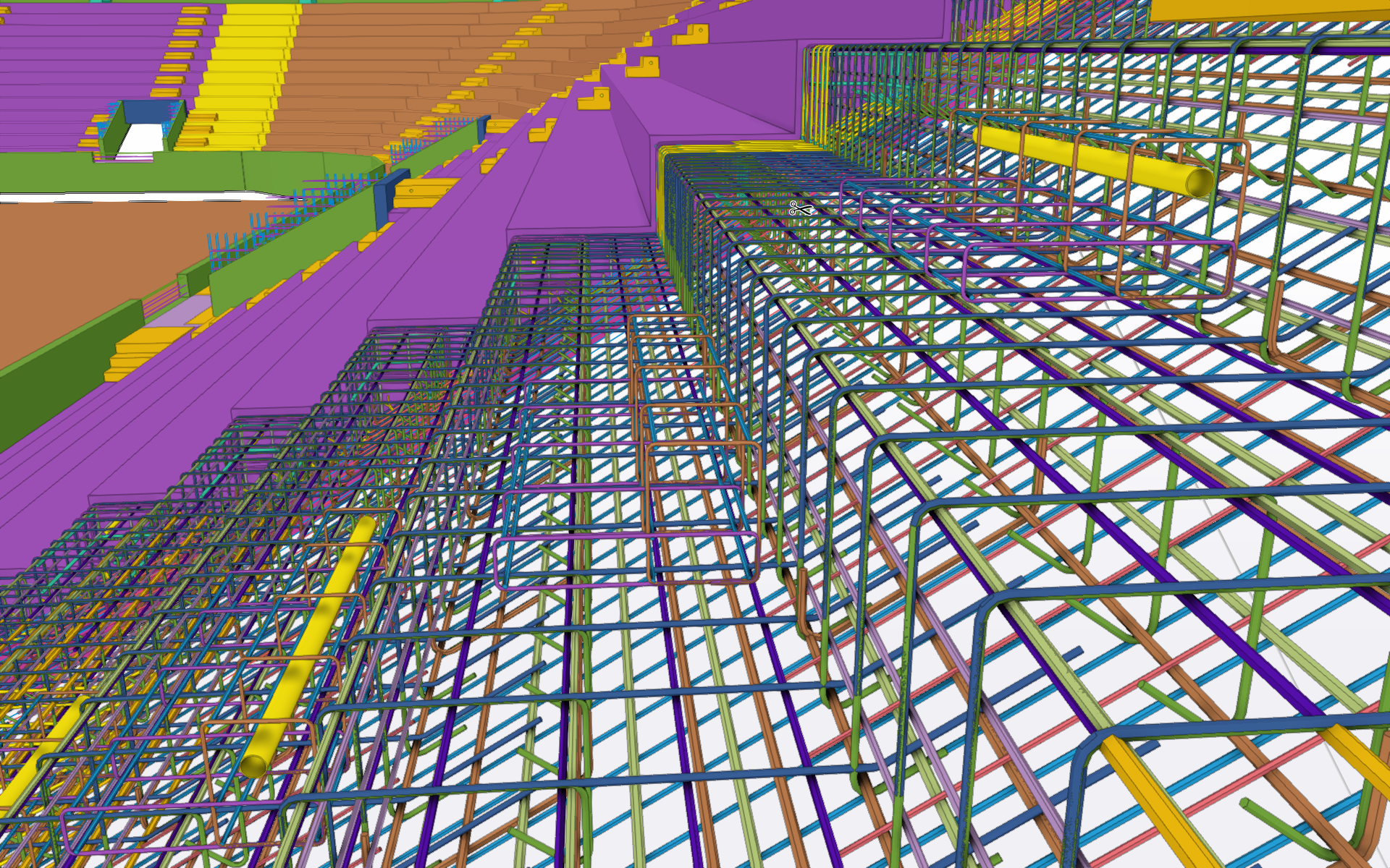
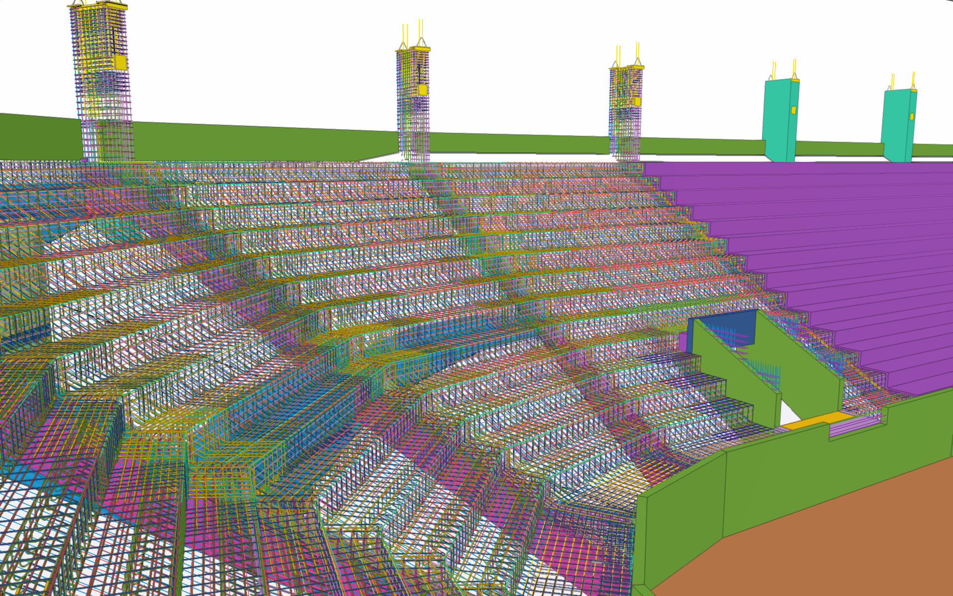
C) Steel and reinforced concrete structures were modeled in the TEKLA Structures program by SKÁLA & VÍT, s.r.o. in one common model. Thanks to this, the coordination of steel and reinforced concrete structures at the point of connection to each other was ensured.
Processed levels of documentation:
1) Change of construction before completion
2) Implementation project
3) Production and assembly documentation of steel structures
4) Supplier documentation of reinforced concrete structures
5) Documentation of the actual execution
D) The Trimble Connect program was used to coordinate professions using 3D models.
REINFORCED CONCRETE STRUCTURES
The foundation
Deep-drilled piles were chosen as a foundation on the basis of an engineering-geological survey. The placement of the piles is based on the arrangement of the upper load-bearing structure. The piles are equipped with monolithic reinforced concrete pad footing, which are connected by monolithic reinforced concrete strip footing for the transmission of horizontal forces and in the places where the brick load-bearing perimeter walls are established.
West stand
The monolithic reinforced concrete three-story skeleton is made up of vertical columns, stiffening wall stair cores and a ceiling reinforced by headers and flat beams. A separate part is the outdoor VIP monolithic inclined tribunes supported by vertical columns and inclined beams. The basic module system of columns is 8.0m in the longitudinal direction, 5.8m + 7.5m + 5.7m + 5.1m in the transverse direction.
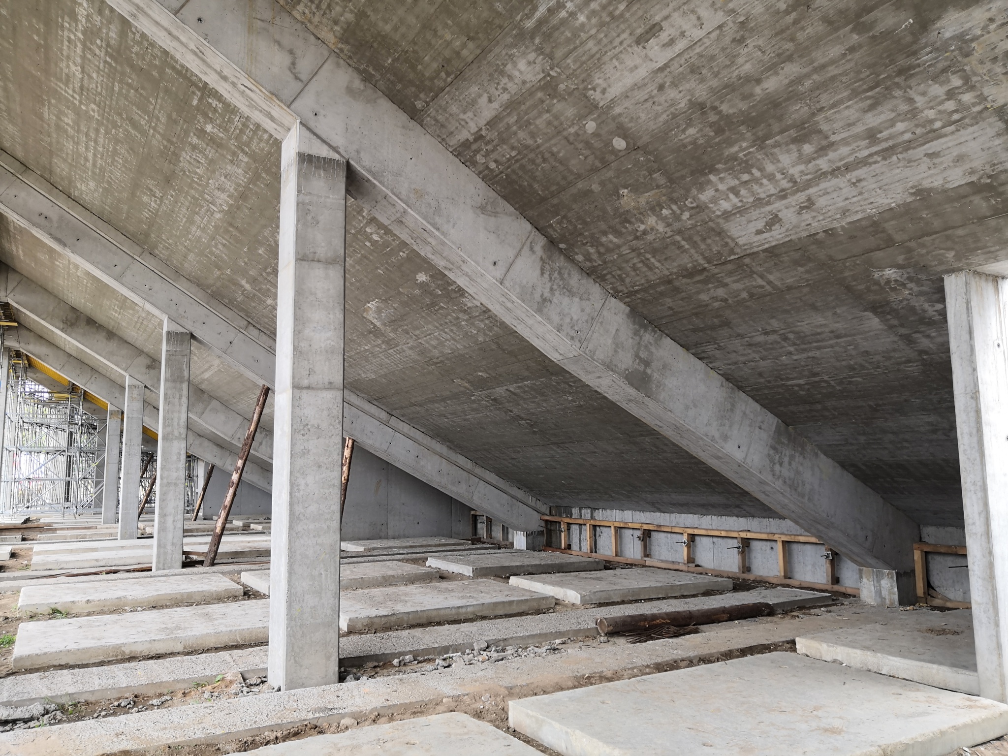
North, East and South stands
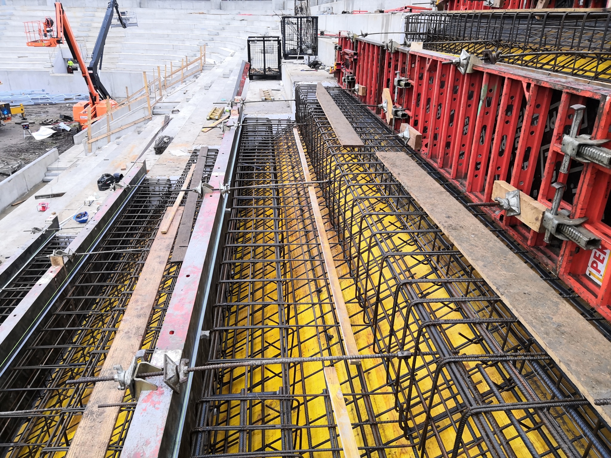
In the transverse direction, the structure of the stands is made up of a monolithic reinforced concrete frame made of three columns and an inclined beam. A monolithic reinforced concrete construction of sloping stands in the shape of steps is placed longitudinally on the frames, which is divided into expansion units. In every other field, there are „moongates“ – monolithic reinforced concrete walls with a staircase. The module axes of the transverse frames are 9.6 m apart on the east stand and 10.1 m on the north and south stand.
Around the entire perimeter, there are built-ins under the stands with a background made up of brick load-bearing walls and a monolithic reinforced concrete ceiling.
STEEL CONSTRUCTIONS
Roof construction
The main supporting element of the steel roof above the stands are galvanized truss-beams with a cantilevered length of approx. 14 m, going from the head of reinforced concrete columns. Trusses are welded from rolled H-shaped cross-sections and diagonals with verticals from rectangular and square hollow cross-sections. The galvanized truss-beam has the shape of a quadrilateral.
The height of truss is the highest above the head of the reinforced conceret and the height is the smallest at the extremity of cantilever. The height above the column is approx. 1,700 mm. The lower belt of truss is inclined into slope towards the outer contour of the stands.
The galvanized trusses of the northern, eastern and southern stands are supported from bottom by galvanized struts of square hollow sections. These struts are located approx. in one-fifth of the cantileverd length of the lower belt os truss and approx. 2 m below the head of the concrete columns.
The galvanized trusses of the western stand are designed in the same sense. The only difference is the roof slope and the absence of struts. The height above the ground at the extremity of cantilevered part is preserved and thanks to lower roof slope the higher level of support on concrete columns is achieved.
At the level of the lower belt of truss there are connected galvanized purlins of square hollow cross-sections. At the distance of 2 m from the truss, the purlins are suspended by tie rods of circular hollow cross-sections suspended from the upper belt of truss. The outer purlin at the extremity of the truss cantilevered part is not suspended but forms a continuous beam.
The transition fields of roof at the west stand where the roof slope changes are created using bent galvanized purlins and a skew galvanized beam to support galvanized trapezoidal sheets.
Under the lower belts of truss and in the middle-span of the purlins there are attached brackets made of circular hollow cross-sections, which carry the beams made of pairs of U-sections oriented along the slope of the roof. The roof galvanized trapezoidal sheets of height 135 mm are inserted into the beam of pairs of U-sections and serves like a bearing part of roof. Wooden boards and PVC waterproofing films are attached to the galvanized trapezoidal sheets.
Behind the football targets on the north and south stands there are structures for fixing the flat screens with dimensions of approx. 6.9 x 10.6 m and are attached to two atypical trusses with additional struts and bracings.
Construction of facades
The facade around the perimeter of the stadium is made up of T-section posts with a variable web height which are welded from metal sheet . The posts are connected at the base to the reinforced concrete wall around the stadium. Next supports of posts are in two levels by thin-walled C-shaped wall rails. The last part of the post forms a cantilever.
Between the posts there are attached metal angles of bent sheet which carry expanded metal sheets with a maximum filling ratio of 50%.
Other constructions
Stairs, railings, platforms, cooling/air conditioning units etc. are made of galvanized steel structures.


Hinterlasse ein Kommentar
Construsoft is an authorized Tekla Structures vendor and provides training, technical support, and other services to its customers.
For more information, please visit our website:
construsoft.comTekla is a Trimble Company © Copyright 2026 Tekla