 Vítěz kategorie v zemích:
Indurating Hood
| Kategorie | Průmyslové projekty |
|---|---|
| Rok | 2023 |
| Země | Czech Republic |
| Organizace | SteelPro 4 s.r.o. |
| Autor | Mr. Žák |
| Spoluautoři | Mr. Bílek, Mr. Zbožínek |
| Místo stavby | India |
| Tags |
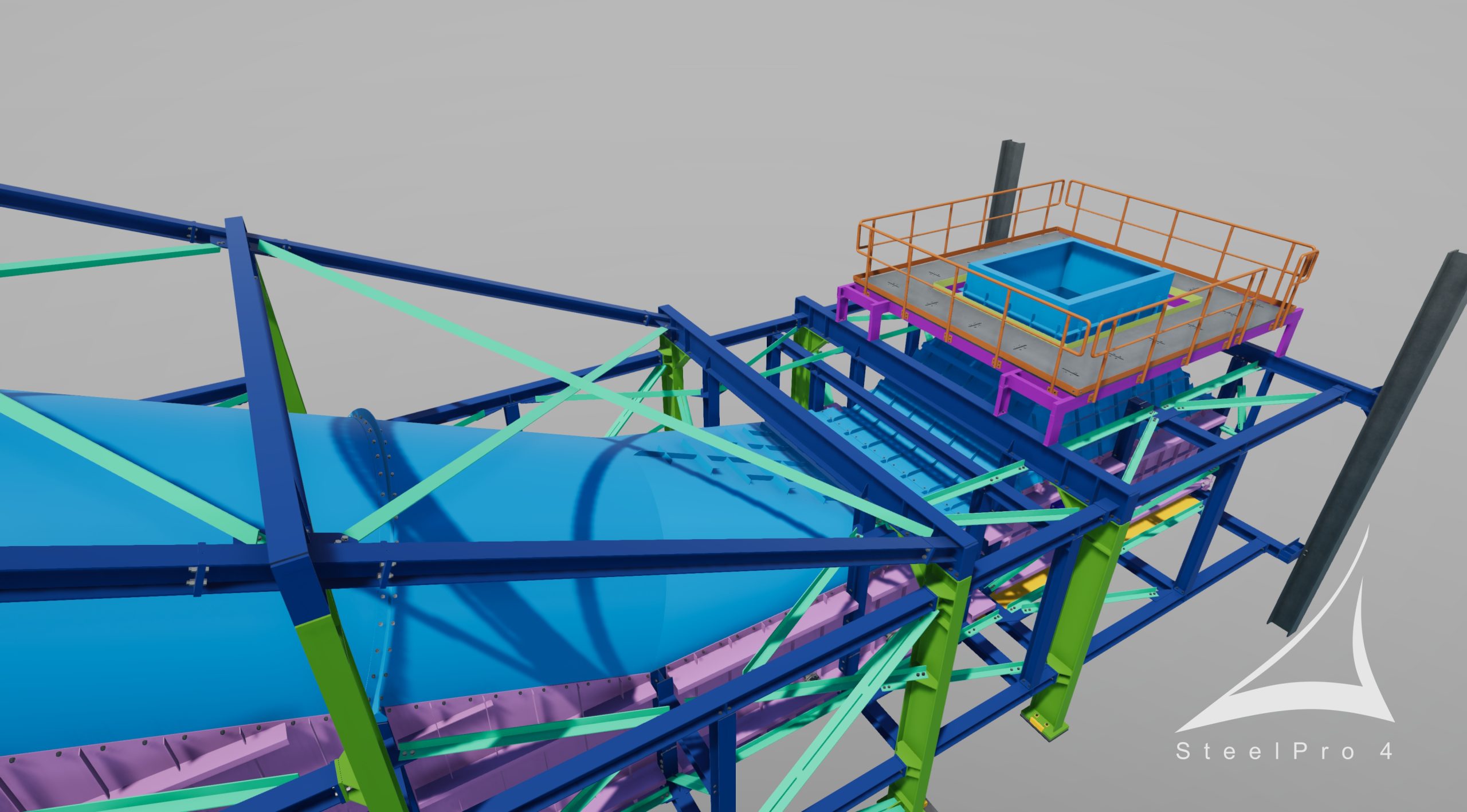
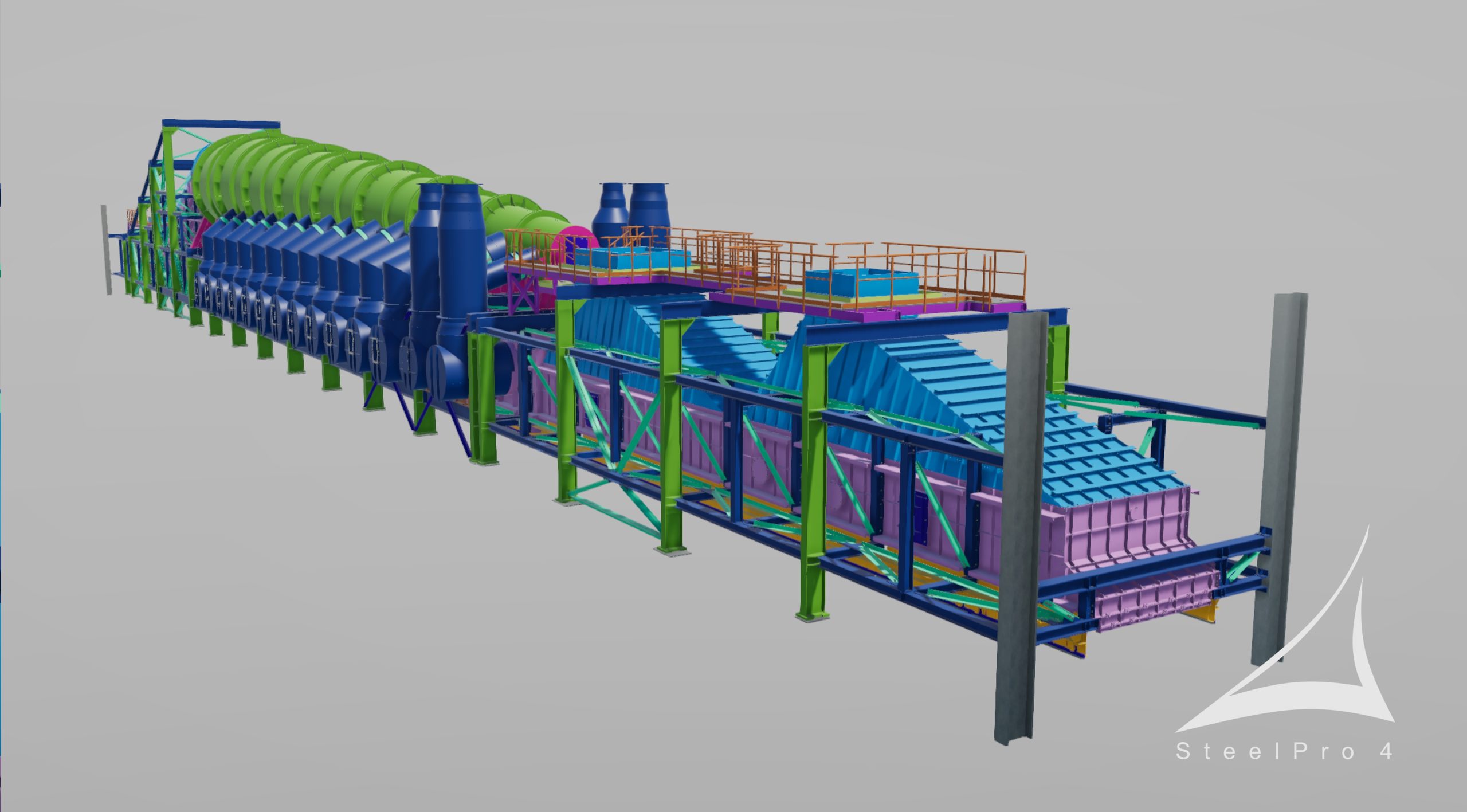
Předmětem dodávky společnosti SteelPro 4 s.r.o. byl statický návrh kompletní konstrukce indurační pece (ocelová konstrukce včetně všech plechových částí), zpracování projekčního 3D modelu, vypracování projekčních výkresů se zobrazením vyzdívky a následné vytvoření výrobních a montážních výkresů dle požadavků objednatele.
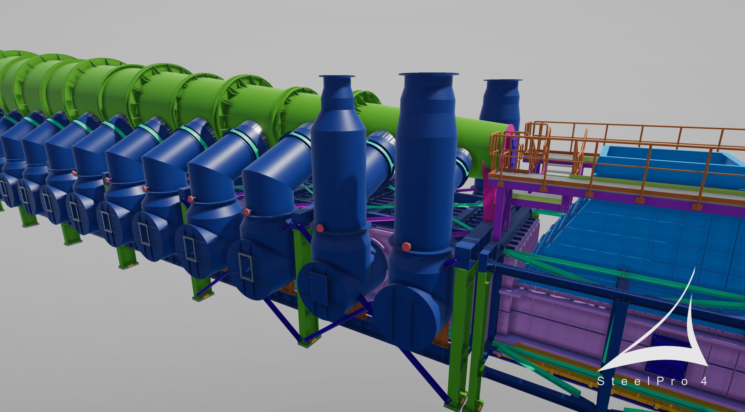
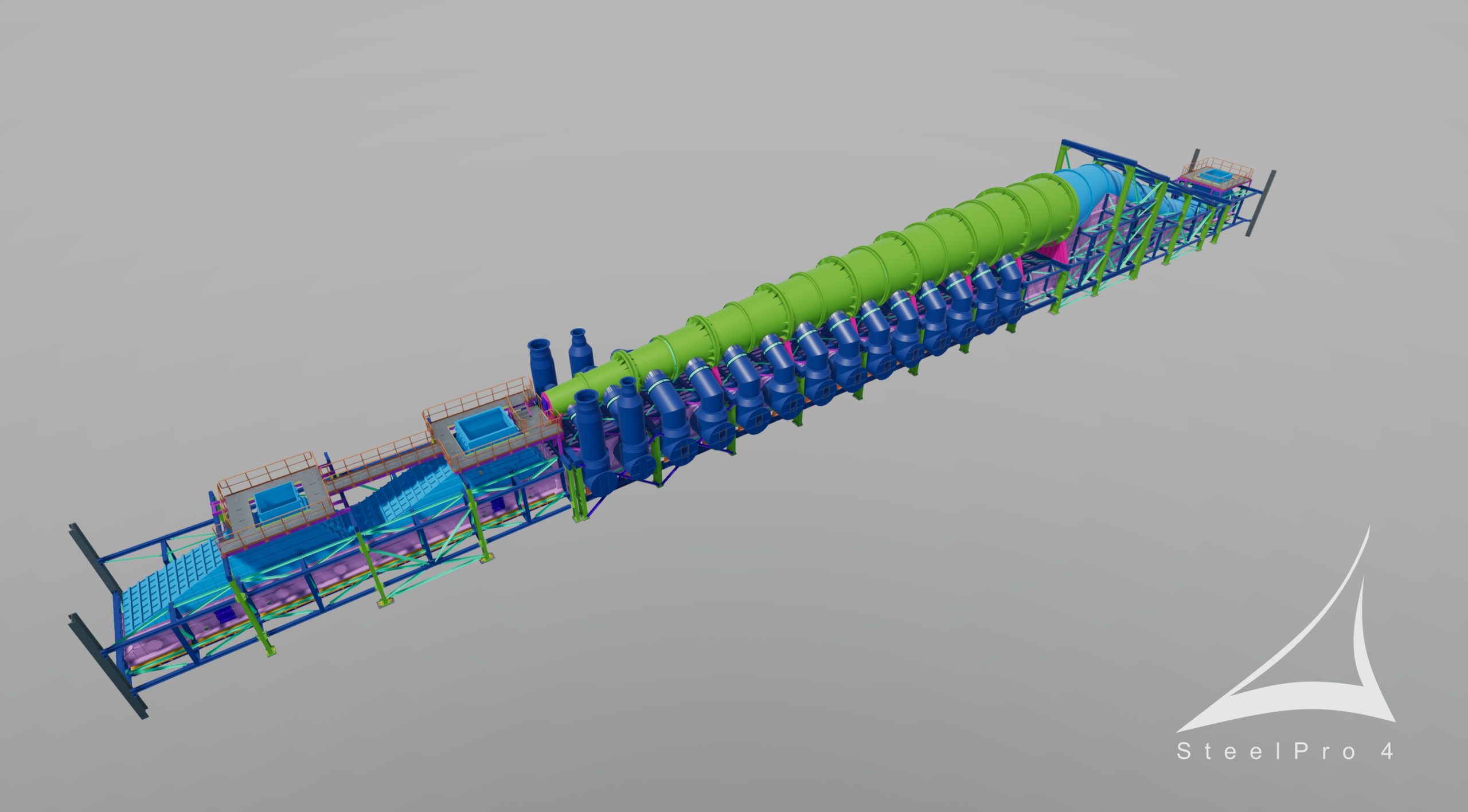
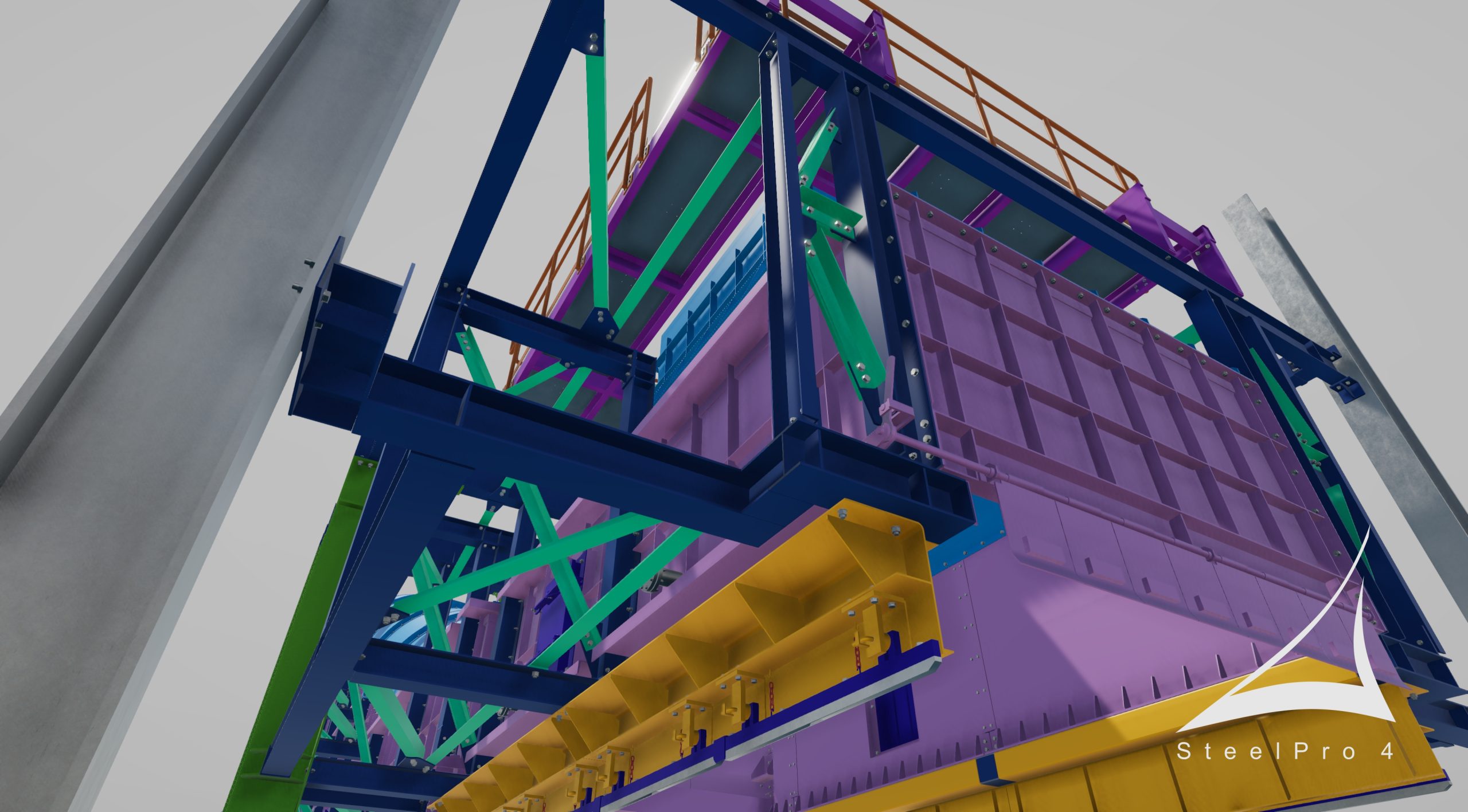
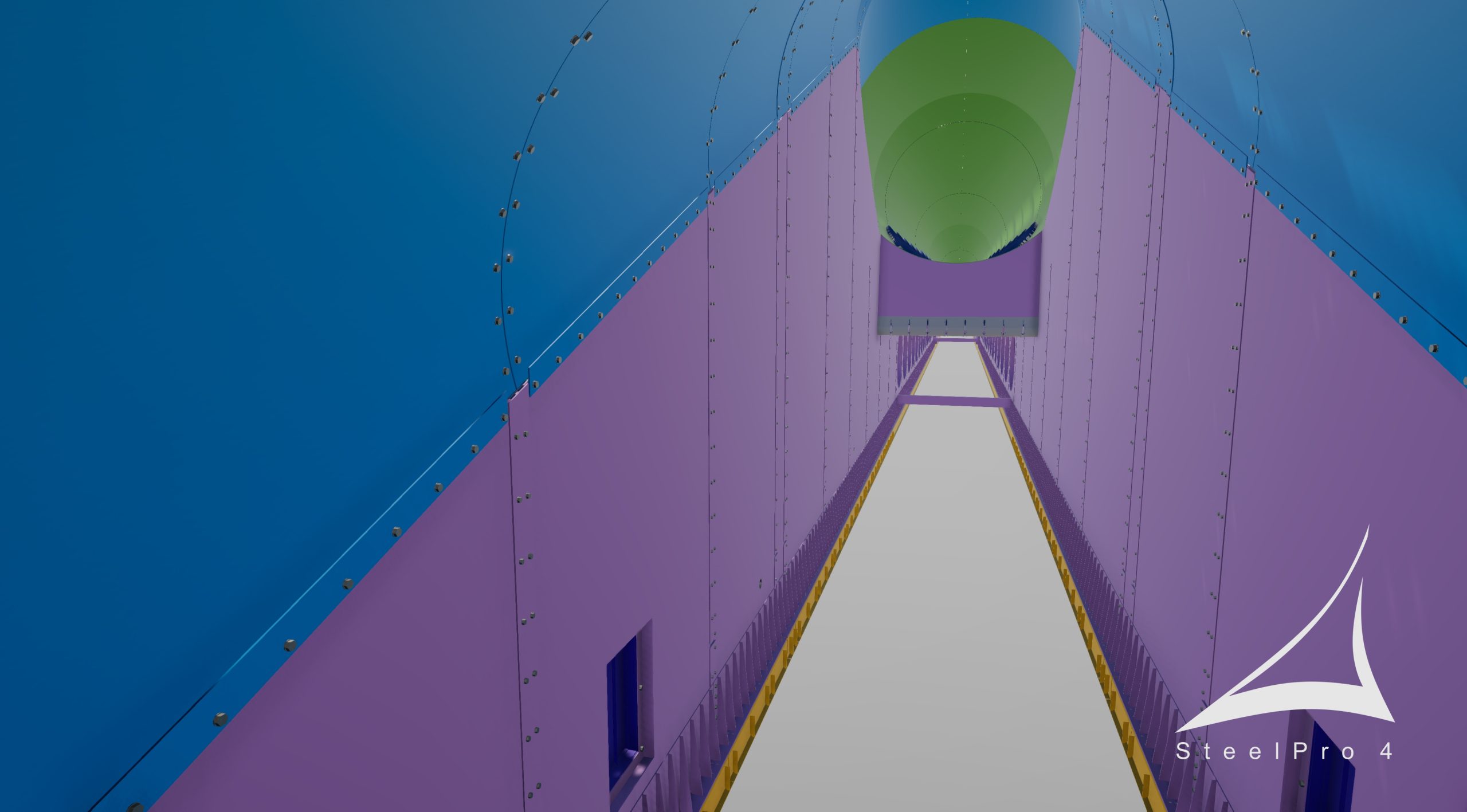
Indurační pec je samostatným objektem v objektu, který slouží ke zpracování železné rudy, kde výsledným produktem po kalení v oxidační atmosféře při teplotě 1250°C jsou tzv. „pelety“. Technologická část je rozdělena do 3 dilatačních celků a je kloubově založena na úrovni +8,985m na zhlaví sloupů hlavního objektu. Veškeré kotvení zohledňuje tepelnou roztažnost a seismické účinky hlavního objektu. Ocelová konstrukce byla navržena jako šroubovaná, plechová část kanálu je připevněna ke sloupkům se zohledněním rozdílné teplotní roztažnosti spojovaných částí. Rekuperační duct (kuželový tubus) navržen jako celo svařovaný na stavbě s uložením na nosnou konstrukci přes ložiska systémem pevné-kluzné-kluzné-pevné. Downcomery pro přívod vzduchu od hořáků navrženy jako celo svařovaný dílec v dílně s finálním ustavením, svařením na stavbě. Pomocné konstrukce pro přepravu a montáž nebyly součástí předmětu dodávky.
Pro vytvoření 3D modelu a výkresové dokumentace byl použit sw Tekla Structures Steel Detailing. Prvky rekuperačního potrubí a downcomerů byly modelovány pomocí funkce lofted plate, v kombinaci modelovaní pomocí sw Grasshopper.
Předávaná dokumentace byla koncipována jako multi výkresy dílců i položek, předávaných ve formátu *.dwg / *.pdf. U souboru DWG bylo nutné použít razítko s předem nadefinovanými bloky pro další „strojní“ zpracování na straně objednatele, které muselo být vyřešeno vytvořením externí aplikace. Výzvou byly kusovníky na montážních sestavách a výrobních výkresech, kde se chvíli nedařilo skloubit výpisy s odlišnou hierarchií. Samostatnou kapitolou bylo splnění požadavku na automatické zobrazení jiného měřítka jednotlivých pohledů, řezů atd., než bylo základní měřítko multivýkresu.
Nesoulad v podobě rozdílných hodnot rozměrů / kót (rozdíl hodnot 1 mm) mezi celkovou kótou a ručním součtem řetězových kót způsobil značné problémy s generováním popisků položek, výkazů a samotným okótováním, protože rozdílné hodnoty nebyly tolerovány a v mnoho případech se hodnoty kót musely posčítat a upravit.
Jedním z důležitých požadavků objednatele byla výměna 3D modelů. S ohledem na požadavek pro výstup ve formátu *.stp bylo zjištěno, že je reálné smysluplně do tohoto výstupu exportovat pouze rovné prvky bez zakružení. Po konzultaci s podporou sw Tekla bylo vydáno oficiální vyjádření k této záležitosti, které bylo předáno objednateli. Objednatel byl nucen pro svoji práci si zakružené prvky přemodelovat a v ostatních případech nebyly do exportů tyto prvky zahrnuty.
Jako drobnost s odstupem času můžeme označit kompletní překreslení rozvinutých tvarů konstrukcí rekuperačního ductu a downcomeru. Při použití funkce lofted plate není možné v rozvinu vytvořit „síť“ pro zakótování rozvinutého tvaru. Celý systém pomocných čar a hodnot byl dodělán ručně s tím, že u prvků šikmo řezaných bylo nutné ručně upravit nejen tvary, ale i hodnoty plechů do popisků, kusovníků.
Tento projekt byl pro naši společnost výzvou jak po stránce statických výpočtů a návrhu detailů, tak také pro správnou tvorbu 3D modelu a navazující výkresové části. Bylo nutné pochopit jak proces samotný, tak také správně aplikovat různé detaily pro „utěsnění“ pece, nebo zajistit její tepelnou roztažnost a zohlednit požadavky ze seismicity.
Díky skvělému teamu a opravdu velké podpoře ze strany objednatele se tento úkol podařilo splnit a věříme, že nově nabyté zkušenosti budeme moci zúročit na dalším podobném projektu.
The scope of SteelPro 4 s.r.o. delivery was the static design of the complete structure of the indurating hood (steel structure including all sheet metal parts), creation of the 3D design model, preparation of design drawings showing the lining and then creation of production and assembly drawings according to the customer’s requirements.
The indurating hood is a separate object in the building, which is used for the processing of iron ore, where the resulting product after quenching in an oxidizing atmosphere at a temperature of 1250°C is the so-called „pellets“. The object is divided into 3 units and is anchored by hinged joints at the level of +8.985m to the columns of the main building. All anchoring takes into account the thermal expansion and seismic effects of the main building. The steel structure was designed as bolted, the sheet metal parts of the duct are attached to the columns taking into account the different thermal expansion of the connected parts. The recuperation duct (conical tube) was designed as an all-welded on-site duct with a fixed-slide-fixed bearing system. Downcomers for air supply from burners are designed as welded parts in the shop with needed alignment, final position welded on site. Auxiliary structures for transportation and assembly were not included in the scope of supply.
To create the 3D model and drawings we have used sw Tekla Structures Steel Detailing. The elements of the recuperation duct and downcomers were modelled using the lofted plate function, combined with modelling in sw Grasshopper.
The submitted documentation was designed as multi drawings for parts and items, submitted in *.dwg / *.pdf format. For the dwg files it was necessary to use a stamp with predefined blocks for further „machine“ processing on the client’s side, which had to be solved by creating an external application. The challenge were the reports on the assembly and production drawings, where for a while it was not possible to reconcile listings with different hierarchies. A separate chapter was meeting the requirement to automatically display a different scale of individual views, sections, etc. than the basic scale of the multi-drawing itself.
Inconsistencies in dimensions / cotations (1 mm difference in values) between one total cotation and the manual sum of the chain cotations caused significant problems with the generation of item descriptions, reports and the cotations on the drawings, as differing values were not tolerated and in many cases the cotation values had to be cross-checked and adjusted.
One of the important requirements was the exchange of 3D models. With regard to the requirement for output in *.stp format, it was found that it was only realistic to meaningfully export straight elements without curves. After consultation with Tekla support, an official statement to this matter was issued and forwarded to the client. The client was forced to remodel the curved elements for their work and in other cases these elements were not included in the export.
As a minor detail with we can mark the complete redrawing of the developed shapes of the recuperation duct and downcomers. When using the lofted plate function, it is not possible to create a „mesh“ for the cotation of unfolded shape. The entire system of auxiliary lines and values was completed manually, and that for mitre-cut elements it was necessary to manually adjust not only the shapes but also the plate values in the descriptions and in reports.
This project was a challenge for our company both in terms of static calculations and detail design, as well as for the correct creation of the 3D model and the subsequent drawing part. It was necessary to understand the process itself, as well as to correctly apply various details to „seal“ the hood, or to ensure its thermal expansion and to take into account the requirements from seismicity.
Thanks to a great team and really big support from the client, this task was accomplished and we believe, that we will be able to capitalize the newly gained experience on another similar project.

Komentáře
Construsoft je výhradní prodejce programu Tekla Structures a poskytuje svým zákazníkům odboré služby: poradenství, školení, programování a zákaznickou podporu.
Další informace naleznete na našich webových stránkách:
construsoft.comTekla is a Trimble Company © Copyright 2026 Tekla