Aeroplex Hangár

| Kategória | Ipari projektek |
|---|---|
| Év | 2021 |
| Ország | Hungary |
| Szervezet | ARC-S Group |
| Projektpartnerek | Weinberg 93 Kft |
| Szerző | ARC-S Engineering & Design Kft. |
| Társszerzők | Weinberg 93 Kft. |
| Ügyfél | Aeroplex Közép-Európai Kft |
| Az építmény helye | Liszt Ferenc Repülőtér, Budapest |
| Tags |
Projekt neve: Aeroplex hangár
Projekt címe: Liszt Ferenc Repülőtér, Budapest
Projekt mérete: 8272 m2 (80×88 m)
Generáltervező: ARC-S Group
Generálkivitelező: Weinberg 93 Kft.
Helyszín:
Az Aeroplex hangár projekt keretein belül cégünk olyan szerkezeti rendszert dolgozott ki, ami a foghíj építési helyszín beépíthetőségét maximalizálta minimális anyagfelhasználás mellett. Természetesen a helyi építési szabályzat által előírt paraméterek is teljes egészében betartásra kerültek. Az épületet két oldalról meglévő és üzemelő hangár épületek, a déli oldalon pedig egy földszintes üzemi épület határolja.
Főbb befoglaló méretek:
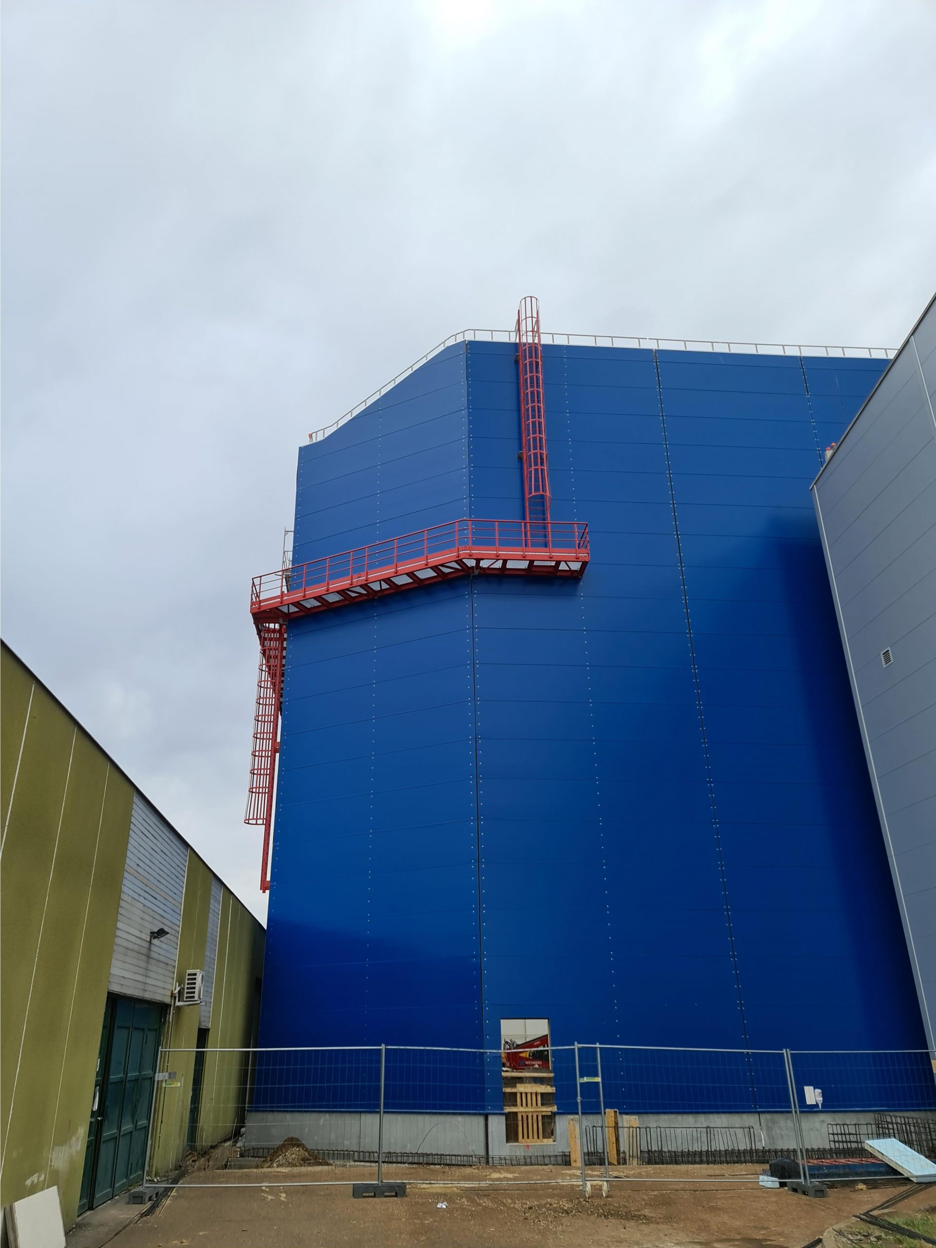
A kialakult egyhajós repülőgép karbantartó hangár vetített alapterülete 8.272 m2, míg fesztávolsága 90 m. Az épület északi homlokzatán kerül elhelyezésre egy 75 m széles 17,5 m magas négytagú hangárkapu. A kapuszerkezet felett középen található egy függőleges vezérsík (farok) bejutását biztosító 5 m*3 m méretekkel rendelkező farokkapu, ami zárt állapotban a főkapu felső vezetősínéül szolgál. Az épület legmagasabb pontja 31 m, míg vállaké ~23,5m. Az északi és déli homlokzaton a csarnok sarka körben ferdén tört, mely a lokális szélterhek csökkentését és a kapu befordulását az oldalsó homlokzatokra hivatott átadni.
Főbb tartószerkezeti méretek:
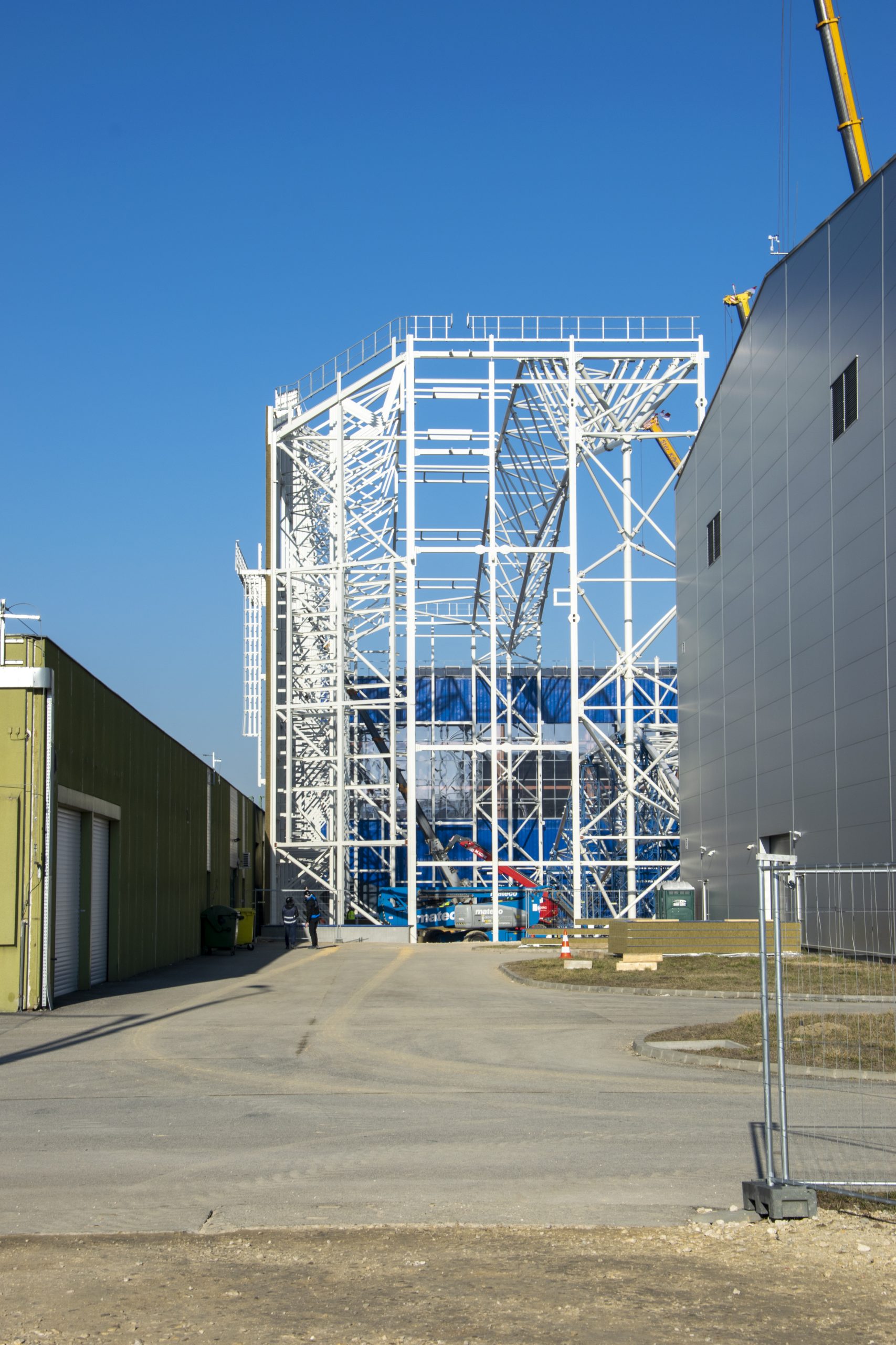
A hangár belső része hosszmentén két különböző magassági szinten daruzott kialakítású. A két szélső traktusban 5 t teherbírású híddaruk, míg a középső harmadban 10 t teherbírású híddaru kerül installálásra. A darupálya közbenső pályatartói a tartószerkezetről lógatott szerkezetként kerülnek kialakításra. A tartószerkezeti rendszer geometriájának tervezésénél parametrikus tervezési eszközöket alkalmaztunk, mellyel többféle rendszer közül választottuk ki a legoptimálisabbat. Az így kialakult főtartószerkezeti rendszer 3 övű rácsostartó keretekből áll, melyek 11,5 méterre találhatóak egymástól, ezen fő keretek között pedig falvázoszlopok kerültek elhelyezésre. Az épület hátfali déli részén síkbeli rácsostartó rendszer került kialakításra, ami önmagában is állékony. A kaputartó szerkezet egy egyedi térbeli rácsostaróként funkcionál.
Az épület alapozása a kereteknél cölöppel gyámolított lemez, a közbenső részeken lemezalap, ami egyben, mint ipari padló került kialakításra.
Az épület dél-keleti sarkánál egy kisebb, szintmagas kiszolgáló épület található a csarnok kontúron kívül, ami 6,7 m x 15 m befoglaló méretű. Az épület külső oldala egyben 2 m-es kinyúlása előtetőként is szolgál.
A területen mért 40 cm tereplejtést a műszaki előtér felé az épület padlója nem követi, így a szomszédos épületekhez való csatlakozásnál lépcsők, rámpák találhatók.
Gyártásra való előkészítés
A gyártási előkészítést a gyártó gyári infrastruktúrája által kialakított számítógépes programkörnyezetben készítettük el, így lehetőség nyílt az automatizált gyártás előnyeit kihasználni, amivel optimálttá vált a lakatolási, vágási és hegesztési időráfordítás. Ezen felül üzemi összeállító szerszámot is terveztünk, melynek segítségével az összeállítási mérések és ellenőrző mérések jelentősen csökkenthetőek voltak. A szerkezetet úgy terveztük, hogy a szállítási rakatolás maximálisan kihasznált legyen.
Szerelés tervezése, Szerszámtervezés
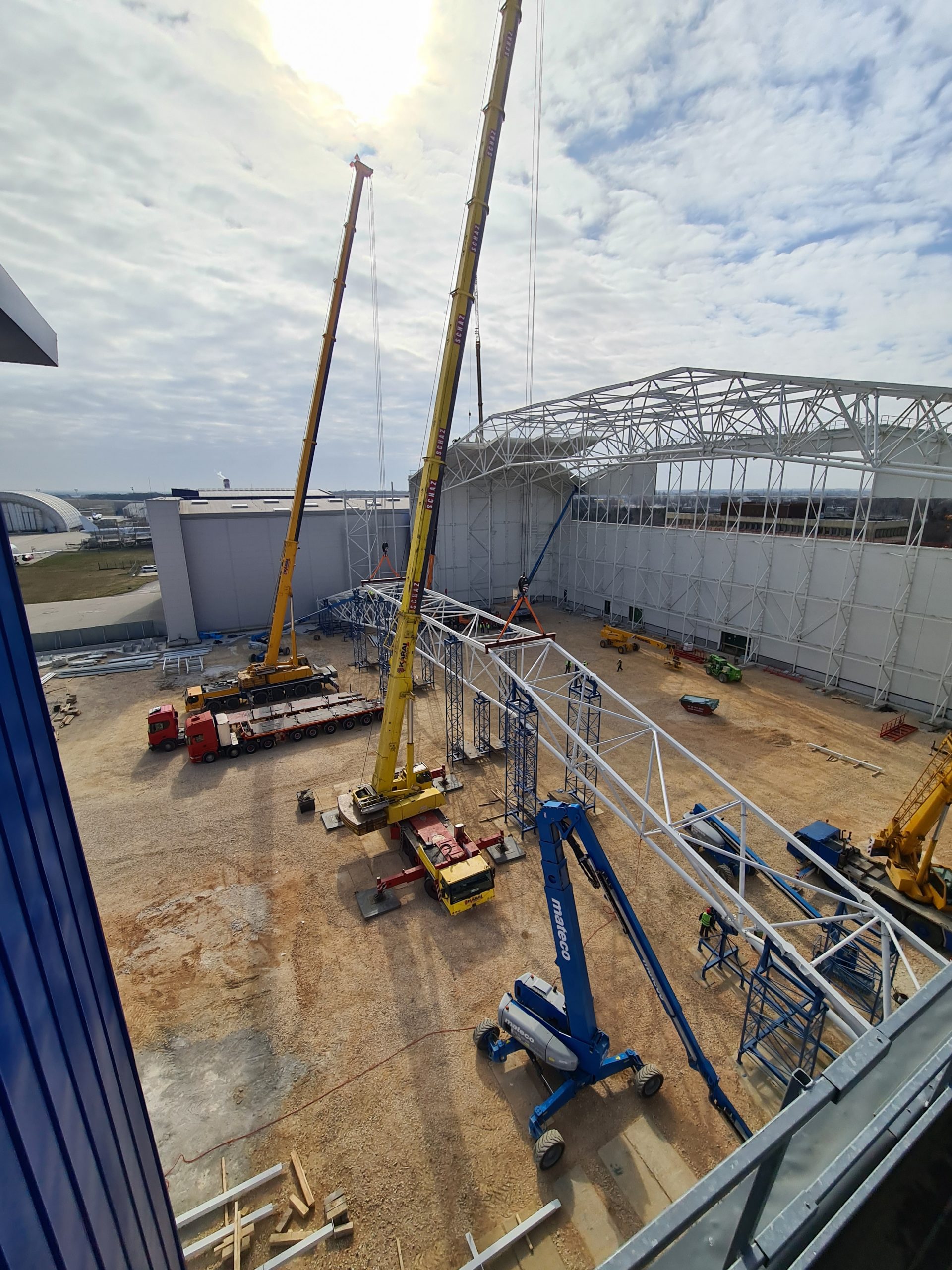
A szerelési technológia tervezésénél megvizsgálva a szűk építési helyszínt az volt a célunk, hogy kis kapacitású darukkal hatékonyan szerelhető legyen a szerkezet, és a szerkezeti szereléssel párhuzamosan haladhasson a burkolás. A helyszínre szerelő szerszámokat terveztük oly módon, hogy azok az összes keretállásnál felhasználhatóak legyenek. A nagyelemes emeléseket két kisebb kapacitású daruval tandem emelésben végeztük, ezáltal egy főtartó beemelése és készre szerelése kevesebb mint 6 napot vett igénybe. A speciális építési helyszín miatt a 90 m-es tartókat a két épület és megépített keretlábak közül kellett kiemelni 10-50 cm emelési mozgáshatárokon belül maradva.
A kapukeret összeszerelése a hangárban történik fektetett állapotban, majd két nagyobb és két kisebb teherbírású daru segítségével első fázisban állóhelyzetbe forgatás történik, ezt követően a két nagyobb teherbírású daru a helyére emeli. Ezek miatt a daruköteleket a ciklusokban nem kell átkötni. Mindezen lépéseket a hangár kapu installációja követi.
A helyszíni installáció során hazánkban elsőként teszteltük és használtuk a Trimble holoLens XR10 technológiát.
Amiért érdemesnek tartjuk a projektet és a teljes csapatot a díjra:
Az összes tervezési fázis során használtuk a Tekla szoftver nyújtotta lehetőségeket, melynek segítségével tervezési és kivitelezési oldalról is hatékony és gazdaságos projektmegvalósulás jött létre.
Project name: Aeroplex hangar
Project’s address: Liszt Ferenc Airport, Budapest
Project’s size: 8272 m2 (80×88 m)
General Architect: ARC-S Group
General Constructor: Weinberg 93 Ltd
Location:
Within of the Aeroplex hangar project our company developed a structural system that made use of the land to the biggest extend possible with minimal material consumption.
Of course, the parameters required by the local building rules were also fully complied with. The building is surrounded by existing and operating hangar buildings on two sides, and on the south side by a ground-story factory building.
Major enclosure dimensions:
The single-aircraft maintenance hangar has a plan floor area of 8,272 m2 and a span of 90 m. A 75 m wide and 17,5 m tall four-piece hangar gate will be located on the north facade of the building. Above the gate structure, in the middle, is a tail gate with dimensions of 5 m * 3 m providing access to a vertical stabiliser, which in closed state serves as the upper guide rail of the main gate. The highest point of the building is 31 m, and the shoulders are 23,5m. On the north and south facades, the corner of the hall was chamfered, which was intended to reduce the local wind loads and the turning of the gate to the sides.
Major support structure sizes:
In the hangar along the length, on two different hight levels has crane design. Two gantries with a load capacity of 5 t will be installed in the two sides tracks, while a gantry with a load capacity of 10 t will be installed in the middle third. The middle tracks for the cranes are designed as a suspended structure from the frames. When designing the geometry of the structural system, we used parametric design tools, where we selected the most optimal from several systems. The main structural system we designed, consists of 3-chord lattice trussed frames, which are located 11.5 meters apart, and between these main frames secondary columns are placed. In the southern part of the back wall of the building, a flat lattice support system has been designed, which is stable in itself. The gate support structure functions as a unique three-dimensional lattice truss.
The foundation of the building is an industrial floor with bored piles at the frames.
At the south-east corner of the building is a smaller, service building outside the hall contour, measuring 6.7 m x 15 m in enclosure size. The 2 m cantilevering extensions serve as canopies.
The 40 cm slope of the site is not followed by the floor of the building, so there are stairs and ramps when connecting to the adjacent buildings.
Preparation for fabrication
The fabrication preparation was done in a computer program environment developed by the manufacturer’s factory infrastructure, so there were opportunities to take advantage of the automated production, which optimized the time spent on cutting, and welding. In addition, we designed a factory assembly tool, which helped to significantly reduce the assembly and control measurements. The structure has been designed to make maximum use of the track’s cargo hold.
Assembly planning, Tool design
Examining the tight construction site during the design of the installation technology, our goal was to be able to install the structure efficiently with low-capacity cranes and to allow the paving to proceed at the same time with the cladding. We designed assembly tools to be used at all frame positions. Large-element lifts were performed in tandem lifting with two smaller capacity cranes, so it took less than 6 days to lift and complete a main girder. Due to the special construction site, the 90 m beam had to be lifted between the two buildings and built trussed pillars with a proximity of 10-50 cm.
The gate frame is assembled in the hangar in the horizontal position, then it is rotated to an upright position in the first phase with the help of two larger and two smaller capacity cranes, after which the two higher capacity cranes are lifting it into place. Because of this, crane ropes do not need to be reconnected in subsequent stages. All these steps are followed by the installation of the hangar gate.
During the installation, we were the first in Hungary to test and use the Trimble holoLens XR10 technology.
The reason why we consider the project and the entire team worthy of the award:
During the phase of design, we used Tekla software which provided us all the help to create an efficient and economical project implementation from the planning and construction side as well.


Hagyja meg véleményét
Construsoft is an authorized Tekla Structures vendor and provides training, technical support, and other services to its customers.
For more information, please visit our website:
construsoft.comTekla is a Trimble Company © Copyright 2026 Tekla